Purpose and principle of operation
The GSM module (Global System for Mobile Communications) uses the operator's telephone network to receive and transmit a signal to a remote control object. For example, using SMS commands you can:
- receive notifications about the state of the object through the sensors used;
- find out when an alarm is triggered;
- turn the security system on and off.
Using GPRS, which is also supported by GSM modules, similar commands can be processed via the Internet.
Using this functionality, you can organize an autonomous alarm system at a remote site. Sensors will record changes in state, and information about this will be broadcast to your smartphone via communication channels. In fact, you can organize a Smart Home yourself, gradually adding additional components to the circuit.
This device operates on the Arduino Uno board. Nobody forbids using Nano (mini-circuit) or Mega boards if necessary, but for the convenience of installing a minimally equipped device, a Uno motherboard is sufficient.
The module that connects to the main board is responsible for GSM or GPRS transmission. It expands the capabilities of Arduino UNO, allowing you to receive and make calls, send SMS, and exchange data via GPRS. There are several versions of excellent GSM boards on the market that can be matched and programmed via AT commands for the required functionality.
Top 6 most popular modules
The modules presented below are a popular product for installing autonomous alarm systems and other projects for transmitting a control signal through the networks of mobile operators.
A module is understood as a product consisting of a board and elements on it (including a component consisting of a chipset and a transceiver). The components are located under the cover in a single form factor (reminiscent of a processor for a computer motherboard). Wiring on the expansion board occurs through the end contact legs. Such a full-fledged board is called a module. If it has many other elements on it, it is sometimes called a shield.
Below we will list modules such as Neoway M590, A6 and A7, and others, and their characteristics will be presented.
SIM900
Developed by SIMCom Wireless Solution, the SIM900 module connects and communicates via the common UART physical data transfer protocol. Connection to a PC is made via a USB-UART converter.
The board allows you to work with messages and calls from the recipient in two-way mode.
Specification:
- Frequency range EGSM900, DCS1800, GSM850, PCS1900.
- Voltage 3.2-4.8 V.
- The current in idle mode is 450 mA.
- Maximum current – 2 A.
- Communication channel up to 14.4 kbit/s.
- Temperature range from -30 °C to +80 °C without distortion, and from -40 °C to +85 °C, with minor RF deviation, while maintaining performance.
- Weight 6.2 g.
- Dimensions 24 x 24 x 3 mm.
The component has modifications: 900B, 900D, 900TE-C, 900R 900X. Each modification has its own specifics. SIM900D is supplemented with a battery charging unit, and SIM900X introduces new energy saving modes, which allows the modules to be used in modern car tracking systems, security and industrial automation. All modifications of components can be found in a single SMT form factor, with solder end contacts. But the possibility of being in other form factors is not excluded.
SIM800L
The basis of the module is the SIM800L component with the implementation of data exchange via GSM and GPRS channels using duplex mode. A SIM card is installed in the module, there is a built-in antenna and an output for another antenna. Power is supplied to the board through a DC-DC voltage converter. It is also possible to connect to another power source. Connection interface – UART.
Specification:
- Quad-band cellular terminal.
- Voltage 3.8-4.2V.
- Standby current – 0.7 mA. Limit current – 500 mA.
- Slot
- Support 2G network.
- Temperature range from -30 °C to +75 °C.
A6
Shield A6 works in mobile networks and allows you to receive and transmit signals using GSM and GPRS. The module created by AI-THINKER several years ago has successfully proven itself and is popular in automation systems.
TTX A6:
- Quad-band cellular terminal.
- Supply voltage 5 V.
- The current in sleep mode is 3 mA.
- Standby current – 100 mA.
- Connection mode current – 500 mA.
- Peak load current – 2A.
- Connector
- GPRS speed during signal transmission is 42.8 Kbps.
- Temperature from -30 °C to +80 °C.
A7
The new A7 module differs from its predecessor in that it has built-in GPS. This solution allowed us to simplify the design of the board.
Main parameters:
- Quad-band cellular terminal.
- Voltage 3.3-4.6 V.
- Supply voltage 5V.
- 10 GPRS class: data channel 85.6 kbit/s.
- Jammer echo and noise.
Neoway M590
The module based on the Neoway M590 component allows you to receive calls, exchange data and messages. Has a UART connection interface.
Characteristics:
- Frequency range EGSM900, DCS1800.
- Grade 10
- Voltage 3.3-5 V.
- Peak current 2 A.
- Operating current 210 mA.
- Communication signal 3.3 V.
- Temperature from -40 °C to +80 °C.
When connecting the module to the controller, a 3.3V -> 5V converter is required.
GSM GPRS module SIM900
Based on the SIM900 module, we developed and successfully use the SIM900 GSM GPRS Shield as a module for connecting to Arduino UNO. Compared to other boards, the cost of this one is much more expensive, and it is equipped with many connectors and contacts. Among the main parameters:
- The board is connected to Arduino Mega and UNO.
- Four operating frequencies, as in other boards.
- Low power consumption 1.5 A in sleep mode.
- GPRS multi-slot class 10/8.
- Operating temperatures from -40°C to +85°C.
Connecting the module to Arduino
You must supply exactly 4.2V to the SIM800 module. I used an LM2596 buck module. We adjust the output voltage to 4.2 V from the potentiometer. Don't forget to connect Arduino GND to LM2596 (-) output. First, connect your Sim800L module to the Arduino;
- NET -> No connection
- VCC -> LM2596 Out (+)
- RST -> Arduino D9
- RXD -> Arduino D7
- TXD -> Arduino D8
- GND -> LM2596 Out (-)
Assembly diagram of a typical Smart Home project
Let's look at options for connecting several GSM modules to Arduino boards. The Arduino UNO and MEGA boards are considered as an example.
Before connecting modules, insert an appropriately sized mobile operator SIM card into the module slot. Next, the module is connected to the main board. To do this, you need to carefully study the instructions, determining the pinout of the modules. After connecting the board to power, using a USB-UART adapter, the controller is connected to the computer, through the Arduino IDE programming environment, or its more convenient alternative, flashed and programmed using AT commands.
Naturally, as the functionality of your project increases, you need to add sensors, relays, sockets and other components to the board. You can read about this on other pages of the site.
Hardware: components
Depending on which GSM module will be used, the components of the circuit also depend.
This is mainly: an Arduino UNO microcontroller, a GSM module compatible with the board, a DC-DC step-down converter (if the communication signal is below 5V), wiring and adapters for connection.
SIM800L + Arduino UNO
For example, to connect SIM800L to Arduino UNO, due to the low voltage of 3.8 V, you need to connect it through a DC-DC converter. The SIM800L module pinout looks like this.
The connection occurs in the following sequence:
- Connect Arduino UNO to your computer via USB port.
- Connect the 12V power supply via DC-DC.
- Minus from the IP to GND of the controller board, and from GND to minus of the converter.
- Plus from IP to plus DC-DC.
- Plus from DC-DC to plus (Vcc) of the GSM module.
- Minus from the ground of the converter to the GND of the module.
- Connect RXD and TXD of the module to pins 2 and 3 of the Arduino UNO.
If necessary, several modules can be connected to any digital pin (digital inputs/outputs).
A6 + Arduino UNO
Since the GSM module has a standard supply voltage, a converter is not needed in the circuit. You can connect the boards directly. The A6 pinout diagram is in the figure below.
The connection occurs as follows:
- UART_RXD of the module to TX→1 of the microcontroller.
- UART_TXD of the module to RX ←0 of the microcontroller.
- GND of the controller with GND of the GSM module.
- Pin VCC0 (power) to the power button on the module PWR_KEY (power).
SIM900 Shield + Arduino MEGA
The peculiarity of the board is that when calling the device, the current reaches a peak limit of 2A. Therefore, do not connect power directly. Before connecting, install a SIM card in the slot and set the TXD and RXD jumpers for the low-current circuit, according to the picture.
Next, connect the boards to each other:
- Connect the yellow wire to the TxD pin.
- Salatov –
- Connect black to GND of the boards.
- Connect the Microcontroller to the PC via the USB port.
To make sure that the circuit is assembled correctly, set GPRS_Shield_Arduino in the IDE.
Checking the correct execution of the circuit looks like this:
- On the Arduino board, connect RESET and ground so that information flows from the Shield to the PC.
- Place the SIM card in the slot and apply voltage to the module.
- Connect the main board to the PC via USB and press the “ON” button.
- If the circuit is operating correctly, the green LED will blink and the red LED will be constantly on.
Software part: sketches and libraries
After disassembling the hardware, you need to program the assembled device. Using text short AT codes, you can issue direct commands to the device. They are perceived by the device while the programmable device is in command mode. The device reads commands directly from the keyboard or using software such as an IDE. The program or its analogues are available for devices running Linux, MacOS, Windows, Android. Therefore, you can also set commands remotely from your phone.
Using the example of programming the SIM900 module, we can consider setting up the basic tools for interaction with a future DIY security project.
Working with SMS notifications
First, set up an encoding that the compiler has no problems with, and then send an SMS:
- Go to the IDE and run the AT+CMGF=1 command to convert the message to text format.
- Then, use the command AT+CSCS=“GSM” to select the ASCII encoding.
- The command AT+CMGS="+79********" is responsible for dialing a message.
- After the command, enter the message text and send it.
- After sending an SMS, press CTRL+Z and the device will send an SMS message to the receiver.
- After the commands are executed correctly, “OK” will return.
To get the message follow the example:
- Send AT+CNMI=2,2,0,0,0 command to read SMS.
- Feedback from the port will be +CMTI: “SM”, 2 – two means the SMS number in the order of priority.
- Send command AT+CMGR=2 to read SMS.
Calls
Naturally, until a microphone and speaker are connected to the circuit, there can be no talk of receiving a call. When the call is made, the number from which the call was made will be displayed. To further work with calls:
- Load the #include library.
- If a PIN is installed on the SIM, then enter the command #define PINNUMBER “”, where write it in parentheses. If the pin is not set, leave the brackets empty.
- After running this command, you should find out the status of the SIM card connected to the network using boolean notConnected = true.
- You can set up activation with the network using begin(). If the connection is ready for use, the feedback will show the status GSM_READY.
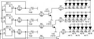
Universal alarm on arduino with SMS sending
Connection diagram:
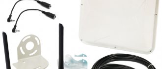
For this project we will need:
Motion sensor: https://ali.ski/EPkJs | Gearbest HC-SR501: https://fas.st/9YvTp
Gas sensor: https://ali.ski/6JRA_ | gearbest: https://fas.st/HB1Ds
Water leakage sensor: https://got.by/1hzcye
Relay module: https://ali.pub/1hzd3n
Zummer: https://got.by/1hzdau
Reed switch (door opening sensor): https://got.by/1hzdjz
Gsm module NEOWAY M590: https://got.by/1hzdsx
In this example, a universal alarm is implemented that sends an SMS to a specific number when a certain action is performed, be it movement or water leakage.
The universal alarm connection diagram itself is presented at the beginning of the article.
After connecting all the components, you need to copy the program code below and paste it into the Arduino IDE program and load this program code into the Arduino board itself.
Sketch:
#include //include the library for software Rx Tx SoftwareSerial mySerial(2, 3); // RX, TX #define pirPin 9 // Declare a variable for the motion sensor and specify the pin int Count = 0; int relay1 = 6; // Declare a variable for relay 1 and specify the pin int relay2 = 5; // Declare a variable for relay 2 and specify the pin int relay3 = 4; //Declare a variable for relay 3 and specify the pin int relay4 = 7; // Declare a variable for relay 4 and specify the pin const int gassensorpin = A5; //Declare a variable for the gas sensor, specify the pin int gassensorvalue = 0; //Declare a variable to store the value from the gas sensor and set it equal to 0 int water = A0; //Declare a pin for connecting a rain sensor unsigned int waterValue = 0; //Create a variable to store values from the water sensor and set it equal to 0 int Door_sensor = 10; //Declare a pin for connecting a door opening sensor int Door_val = 0; // Declare a variable to store the sensor state int buzzer = 8; //Declare a variable for the piezo emitter, specify the pin void setup() { pinMode(pirPin, INPUT); // Assign the motion sensor pin as an input pinMode(Door_sensor, INPUT); //Assign the door opening sensor pin as an input pinMode(relay1, OUTPUT); //assign the pin as a relay as an output pinMode(relay2, OUTPUT); //assign the pin as a relay as an output pinMode(relay3, OUTPUT); //assign the pin as a relay as an output pinMode(relay4, OUTPUT); //assign the pin as a relay as an output delay(2000); //time to initialize the module Serial.begin(115200); //port speed Serial.println("Signalization v1.0"); mySerial.begin(115200); mySerial.println("AT+CMGF=1"); //SMS encoding mode - normal (for English) delay(100); mySerial.println("AT+CSCS=\"GSM\""); //text encoding mode delay(100); } void loop() { gassensorvalue = analogRead(gassensorpin);//Read the value from the gas sensor if (gassensorvalue >= 600) // set the gas level threshold { mySerial.println("AT+CMGS=\"+71234567890\"" ); // give a command to send SMS delay(100); mySerial.print("gas"); // send the text mySerial.print((char)26); // character that ends the transfer Serial.println("ok"); tone(buzzer, 1915); //Send a signal with a piezo emitter delay(3000); digitalWrite(relay1, LOW); // Turn on the relay to which the fan is connected delay(15000); } else { digitalWrite(relay1, HIGH); //Turn off the relay with the fan noTone(buzzer); //Turn off the piezo emitter signal } int pirVal = digitalRead(pirPin); if(pirVal == HIGH) // If movement occurs { mySerial.println("AT+CMGS=\"+71234567880\""); // give a command to send SMS delay(100); mySerial.print("Motion"); // send the text mySerial.print((char)26); // character that ends the transfer Serial.println("ok"); digitalWrite(relay2, LOW); //then Turn on the relay to which the lighting is connected digitalWrite(relay3, LOW); // turn on the relay to which the lighting is connected digitalWrite(relay4, LOW); // turn on the relay to which the lighting is connected tone(buzzer, 1700); //Send a signal with a piezo emitter delay (10000); } else { digitalWrite(relay2, HIGH); //Turn off the relay digitalWrite(relay3, HIGH); //Turn off the relay digitalWrite(relay4, HIGH); //Turn off the relay noTone(buzzer); //Turn off the signal } waterValue = analogRead(water);//Read the values from the rain sensor if(waterValue<300) //set the threshold value for the alarm { mySerial.println("AT+CMGS=\"+1234567890\"") ; // give a command to send SMS delay(100); mySerial.print("Water!"); // send the text mySerial.print((char)26); // character that ends the transfer Serial.println("ok"); tone(buzzer, 1000); //Send a signal with a piezo emitter delay (10000); } else { noTone(buzzer); //Turn off the signal } Door_val = digitalRead(Door_sensor); //Read the values from the door open sensor if (Door_val == LOW){ //The door is open digitalWrite(Door_sensor, LOW); { mySerial.println("AT+CMGS=\"+71234567890\""); // give a command to send SMS delay(100); mySerial.print("Dooropen"); // send the text mySerial.print((char)26); // character that ends the transfer Serial.println("ok"); tone(buzzer, 1700); //Send a signal with a piezo emitter delay (5000); } } else { noTone(buzzer); //Turn off the signal } }
Link to the sketch: https://yadi.sk/d/5drVRxcv3JaLvB
A demonstration of how this program works can be seen in the video at the end of the article.
Video:
conclusions
Building a self-contained GSM alarm system will not be difficult for non-technically savvy people in matters of electrical and circuit design. After reading the instructions and familiarizing yourself with the pinout of the circuits, you can connect the microcontroller to the module responsible for GSM data transmission. Also, various models of GSM modules are available for connection, which, in accordance with their characteristics, can be used for various tasks and so-called project objects.
Regarding programming of controllers, there will be no problems with this either. Using libraries, AT commands and sketches, you can determine the status of a SIM card, receive and send SMS messages, receive calls, and so on. This is done in the Arduino IDE programming environment or in similar environments installed on a remote device, which can be either a smartphone or a computer that is directly connected to the device being programmed.
Lesson code
Open a blank Arduino sketch and download the code below:
#include SoftwareSerial mySerial(8,7); // Change These Pins if you make different wiring void setup() { Serial.begin(19200); //Serial.println(“Begin”); mySerial.begin(19200); } void loop() { if (mySerial.available()) Serial.write(mySerial.read()); if (Serial.available()) mySerial.write(Serial.read()); }
Open AT Command Tester Tool. Click Find Ports and select the correct port. Select "BaudRate" as 19200. After selecting the device port and the correct baud rate (serial port speed), click "Connect" on the AT Command Tester. The tool will send a request to the device and connect.
Registration of the device on the network is required before establishing a data connection. In the Network Selection section, the device can be configured for manual or automatic registration.
In the Voice Call tab, you can check your outgoing and incoming voice calls. The tool provides an easy-to-use interface for dialing outgoing numbers and receiving incoming calls.