Miles is an Arduino Nano-based spider robot that uses 4 legs to walk and maneuver.
8 SG90/MG90 servomotors are used as leg drives. A specially made board allows you to control the motors and supply power to them and the Arduino Nano. The board has special slots for IMU modules, Bluetooth and an infrared sensor, which gives the robot autonomy. The body is assembled from 2 mm thick plexiglass cut on a laser cutter, but it can also be printed on a 3D printer. An excellent project for enthusiasts studying the topic of inverse kinematics in robotics. Inspired by the mePed project (www.meped.io), and uses code based on it.
Materials
Components:
- Fee (1)
- Miles components for assembling the case.
- SG90/MG90 servomotors (12)
- Aduino Nano (1)
- LM7805 voltage regulator (6)
- Switch (1)
- 0.33uF electrolytic capacitor (2)
- 0.1uF electrolytic capacitor (1)
- 3.08mm 2 pin Phoenix connector (1)
- Male connectors for servomotors.
Optional:
- 2 pin Relimate connector (1)
- 10 pin Relimate connector (1)
- 4 in connector Relimate (1)
Step 1: designing the circuit and board
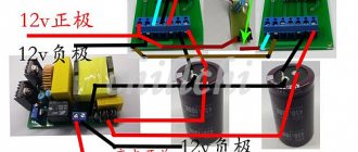
I design my boards in Altium. 12 SG90/MG90 servos can draw up to 4-5 A when running simultaneously, so the circuit must be able to handle high currents. I used 7805 voltage regulators to power the motors, but each one can only supply a maximum of 1A. So I connected 6 LM7805s in parallel, increasing the available output current.
Download diagrams and Gerber files from the link.
Features of the scheme:
- MPU6050/9250 are used to measure angles.
- Output current up to 6 A.
- Isolated power supply for servomotors.
- Output for ultrasonic sensor HCsr04.
- There are peripherals for Bluetooth and I2C/
- Relimate has all analog contacts for sensors and actuators.
- Outputs from 12 servomotors.
- Indicator LED.
Board Features:
- 77 × 94 mm.
- 2 ply FR4.
- 1.6 mm.
Components
To create a robot that will follow a line on the floor, we will need the following hardware :
- Arduino UNO × 1
- SparkFun Dual H-Bridge Driver for L298 Motors × 1
- DC motor, 12V × 1
- Battery holder, 18650 x 2 × 1
Hand tools :
- Soldering iron (universal)
- Drill
- Automatic digital multimeter
- Multitool, Screwdriver
- Pliers
Software
- IDE Arduino
This robot car will follow the contrasting line on the floor wherever it goes. The sensors detect the line (color), the Arduino processes the sensor readings and then tells the motors how and where to move.
Instructions for assembling a spider robot. Part 1.
Step-by-step instructions for assembling and initially setting up the chassis of a six-legged spider robot on Arduino (RKP-RCS-2013B-KIT). Part one.
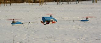
Rice. 1
This image (see Fig. 1) shows an example of an assembled six-legged spider robot with additional equipment installed on the top board in the form of a Bluetooth module for wireless external control.
Step one is preparing to assemble the spider robot.
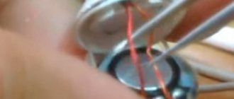
Power supply for the servo control board of the spider robot RKP-RCS-2013B-KIT.
Use copper wire (sold separately, silicone wire 20AWG (0.5 sq. mm) red, 1 m (article RCK049020) =>>) in red insulation and two MAMA type lugs included in the delivery kit.
Rice. 2
Having carefully stripped the insulating layer at the ends of two conductors (of the same length, approximately 5 cm) and crimped the tips, we obtain the first necessary parts for the power supply circuit of the spider robot (see Fig. 3).
Rice. 3
To create the next element of the power part of the circuit, we will need the following supplied with the kit: a toggle switch and a copper conductor in red insulation approximately 12 cm long. You will also need to separately purchase a mating connector with power wires for your battery in order to use it in the power circuit we are creating. We will use an inexpensive JST type connector with soldered red and black conductors (the length of the conductors on the connector is approximately 10 cm).
You can purchase the specified connector with conductors here =>>
We chose the JST connector type specifically, since it is a very common and lightweight connector that is designed for currents up to 10A, which fully satisfies the specifications of the RKP-RCS-2013B-KIT spider robot we are creating.
For assembly we will use a soldering iron! It is necessary to solder the positive contact of the battery connector to the middle contact of the switch toggle switch (see Fig. 4).
Rice. 4
As a result, upon completion of the assembly of this element of the power supply unit of the six-legged robot, the following part should be obtained (see Fig. 5).
Rice. 5
To connect the power supply from the battery via the power switch to the servomechanism control board, you must use the supplied diode rectifier block.
To simultaneously control eighteen sub-micro servos (steering gear 9 Gram GOTECK GS-9018), we will use the very common Servo Controller Board 32 Channel USB servo controller. The general diagram of connecting the power supply of the spider robot to the servo controller board is shown in the image below (see Fig. 6).
Rice. 6
Attention!
Before installing the servos (18 pieces of GS-9018 Sub-Micro Servo) directly onto the platform of the six-legged spider robot, they must be adjusted via the USB servo controller for Arduino RKP-SCB-32C so that all servos are in the middle central position. Otherwise, the steering machines (servos) will NOT work correctly!
Having connected all 18 servos to the RKP-SCB-32C servo controller and properly powered it from a Li-Po battery, you need to connect it via a USB port to a personal computer on which special software is installed for setting up and adjusting the servos.
You can download the software for programming the servo controller in the article “Software for programming the servo controller for 16 and 32 servos =>
All 18 servos should be set to the middle position of the sliders as shown below (see Fig. 7).
Rice. 7
Attention!
Once this center position adjustment is complete, ALL servos must be disconnected from the Servo Controller Board 32 Channel USB (RKP-SCB-32C).
The next step is to directly begin assembling the chassis of the six-legged robot.
We begin, of course, by assembling the supporting platform of the walking robot. The central supporting platform of the spider robot is designed for installing various robot control elements (control boards, sensors, etc.), as well as robot power supply elements (batteries, rectifiers, switches and stabilizers).
The central supporting platform of the walking spider robot on Arduino consists of two milled aluminum plates fastened together with brass stands. This ensures high precision and reliability for the entire spider robot design and is at the same time the best weight ratio solution for accommodating the payload.
Attention!
An important step is to select the correct robot chassis bottom plate. At the first stage, we will need the bottom plate to properly assemble the supporting platform and install additional equipment and batteries for the six-legged spider robot on it.
The image shows, for comparison, the visual difference between the lower and upper boards of the set (see Fig. 8).
Rice. 8
We remove the protective polyethylene film from the aluminum parts. Be sure to determine (according to the pattern of milled holes) the LOWER chassis board and install M2 brass posts 6 mm long. 6 pieces in total, securing them with M2 steel screws 5 mm long (see Fig. 9).
Rice. 9
The installation locations for all six brass posts (M2x6) are shown in the image (see Figure 10).
Note!
All the necessary elements are included in the kit for self-assembling a spider robot on Arduino.
Rice. 10
The next step in assembling the carrier platform is to install the D25XB60 diode bridge on a special standard hole (contacts forward, flat side to the chassis).
Diode bridge D25XB60 - maximum current 25A, maximum voltage 600V.
View the datasheet of the D25XB60 diode bridge (PDF format, size 430 KB)
After installing the D25XB60 diode bridge on the center plate of the spider robot chassis, as well as two brass stands (M2x6) one on each side of the D25XB60 diode bridge, the assembled part of the walking robot's supporting platform should look as shown in the image (see Fig. 11).
Rice. eleven
The first six installed brass struts, in addition to providing structural rigidity to the central platform, are also designed to prevent any displacement of the 7.4V (2S) LiPo battery during the walking robot's movements over rough terrain.
The 7.4V (2S) LiPo power battery must be sized to fit snugly around the installed six brass posts (M2x6) as shown in the image (see Fig. 12)
Rice. 12
The next step is to install four nylon stands designed to mount the Servo Controller Board 32 Channel USB (RKP-SCB-32C).
Note!
All the necessary elements are included in the kit for a self-made spider robot on Arduino (RKP-RCS-2013B-KIT).
The stands for mounting the servo controller are made of special material nylon-66 (UL), have a length of 18 mm, a hexagon shape and an internal thread M3 × 0.5.
It is necessary to secure four nylon posts through the holes made (bottom board only) using M3x6 screws as shown in the picture (see Fig. 13).
Note!
Holes for fastening (using nylon stands) a control controller selected independently and differing in size from the recommended servo controller Servo Controller Board 32 Channel USB (RKP-SCB-32C) are made independently. The holes are made based on the dimensions and dimensions of the holes of the selected servo controller to control the spider robot.
Rice. 13
The next assembly step is to connect a USB/PS2 switch to the servo controller board. To connect, you need to use three flexible wires for prototyping, which have a MAMA-type connector at the ends of the wire for connection to the pins located on the Servo Controller Board 32 Channel USB servo controller board (RKP-SCB-32C). You will need to use a soldering iron to solder the return ends from the three flexible breadboard leads to the three contacts of the dip switch. The diagram shows which pins on the RKP-SCB-32C servo controller board to connect the two-position switch to (see Fig. 14).
Rice. 14
The length of the flexible wires used for prototyping must be sufficient so that tension on the wire is not created and the pins on the servo controller board to which they are connected are not bent. Installed flexible conductors for prototyping can have different colors.
Breadboard wire sets are purchased separately =>>
The image below shows the length of the wires and the location of the DIP switch (see Figure 15).
Rice. 15
Next, you need to use the brass stands included in the delivery kit, 4 pieces M2x20 (female-female type) and 4 pieces M2x20+3 (female-male type) (see Fig. 16).
Rice. 16
By twisting them together, we get 4 racks with a length of 4 centimeters.
Pay attention to precise measurements when choosing brass struts M2x20 (male-female type), since the chassis of the six-legged spider robot RKP-RCS-2013B-KIT also includes brass struts 21 mm and 23 mm long, which are installed in the legs of the spider robot (second part of the step-by-step instructions).
You need to twist the racks 4 pieces M2x20 (male-female type) and 4 pieces M2x20+3 (male-male type) in pairs as shown in the image (see Fig. 17).
Rice. 17
Having thus assembled all four 4-centimeter-long stands, you need to attach them with four M2x5 screws to the bottom board of the spider robot in special holes, as shown in the image (see Fig. 18).
Rice. 18
Continuation of step-by-step instructions for assembling a spider robot on Arduino (part two) =>>