Gromov programmer
The first question you want to ask directly is what is a “programmer” ? The word “programmer” is formed, oddly enough, from the word “program”. What is a program? If you remember what a TV program is and why it was needed (by the way, it is still sold in kiosks), then it becomes clear that the TV program is the time schedule of these same TV shows. This means that a program can be called some actions or events that will be performed one after another in time, when we want it or not. Therefore, a programmer is just some kind of device that allows us to write or read a program. Only the programmer himself can change the program
CM
For beginning radio amateurs, the transition from assembling simple analog devices, such as multivibrators, to assembling devices using MK can be difficult because it is not enough to simply wire and solder the device on a printed circuit board; you also need to upload the firmware into the microcontroller’s memory using a programmer . As has already been written in previous articles, a microcontroller, until we “uploaded” the firmware into it, is simply a useless piece of silicon. And then a novice radio amateur is looking for information on the Internet about assembling a simple but effective programmer that would help him get a quick start in this difficult task.
I will not be mistaken if I say that 80% of beginners, if they have a COM port on their computer, assemble the Gromov Programmer . This scheme, with its simplicity and skillful handling, is a real masterpiece). Indeed, in order to assemble a programmer with your own hands, connected to a USB port and containing an AVR microcontroller, which must be pre-programmed, you again need a programmer. Where can a beginner get a programmer, even for such a one-time firmware? It turns out to be a chicken and egg paradox), in order to assemble a USB programmer, we first need to program the microcontroller of the programmer))).
So, let's look at what exactly is flashing a microcontroller (MK) using a programmer, and how is it done? In order to flash the MK, we need a combination of the programmer itself, a device soldered on a printed circuit board, and a program called a shell that works with this device.
Gromov programmer
Each type of programmer most often requires its own software shell. To assemble the Gromov programmer, you do not need to program the microcontroller. This programmer does not have it. This programmer works with two widely used flashing shells: PonyProg and Uniprof . We will have separate reviews of these programs. This programmer is connected to the COM port. The only obstacle to its assembly may be the physical absence of this connector on the motherboard of your system unit. Why the system unit? Because laptops, as well as modern models of motherboards produced in 2010–2011 and higher, often have a reduced supply voltage on the COM port contacts. What does this mean? This means that you can assemble this programmer, but it will not work for you. But with computers manufactured in 2007–2008 and older, with the exception of laptops, this programmer should be guaranteed to work. Connecting via USB - COM adapters does not help in this case, since at best there is a strong decrease in speed, and at worst, the programmer refuses to work at all.
Let's look at the circuit diagram of the programmer:
What do we see in this diagram? COM port connector, otherwise called DB9, 7 resistors of the same value with a resistance of 1 kOhm and a power of 0.25 Watt and 3 pulse diodes. The suitable diodes are either domestic ones, KD522, KD510, or imported 1N4148.
Let's look at what these radio components look like.
The photo below shows the DB9 connector:
As we can see, the pins (terminals) of this connector are indicated by numbers on it. If there are any difficulties in determining which pin corresponds to which hole of the connector, I recommend inserting a wire into the hole of the connector pin, switching the multimeter to the audio test mode and simultaneously touching the wire with the multimeter probes to each of the pins on the connector in turn, and checking the correspondence of the pins to the holes. This may be required if you are connecting the connector with wires to the board. If the connector is soldered directly to the board, then these steps are not required.
Those who do not have a COM connector on the motherboard connector panel located at the back of the computer can buy brackets with such a connector. But you need to make sure that the manufacturers have soldered the COM port controller to the motherboard, and provided for connecting the cable of this strip directly to the board. Otherwise, this option will not help you. As an alternative, I can suggest purchasing a COM port controller located on a special expansion card, which is installed in the PCI slot of the PC
Also, if you wish, if you want the cable connected to the COM port to be disconnected from the programmer, you can unscrew the fastening screws, remove the connector from the bracket, and secure it in the programmer body. But be careful, and after purchasing, ring all the wires to match the numbers on both ends of the cable, because cables that are similar in appearance and have crossed wires are often on sale. The cable for connecting to this connector must be fully wired, DB9F - DB9F, straight, not crossed, the connector will not work with other cables.
If you have problems purchasing this cable, you can take a crossed cable or a 9M-9F extension cable, but in this case you may need to cut the connector at the other end and solder the wires along the pins of the connector directly to the programmer board. By the way, I had just such an extension cable, and I had to cut the connector from the second end. Do not buy cables for flashing phones via the COM port; they are not suitable for our purposes, since the wiring is incomplete.
Go ahead.
We take KD522, KD510 or 1N4148 diodes. This is what the KD522 diode looks like
Be careful, the diode has a switching polarity. In other words, it doesn’t matter how you solder it, you can solder it backwards, then the programmer will not work. As you know, a diode has a cathode and an anode. The cathode is marked, in this case, with a black ring.
Well, with resistors, I think there will be no problems. Go to a radio store and tell the seller: “I need 1 kOhm 0.25 Watt resistors.” It is advisable to take imported resistors, since domestic MLTs have a greater deviation from the nominal value.
If you know the LUT method, then it will not be difficult for you to assemble a programmer using this printed circuit board. Below is a screenshot of the board from the Sprint Layout program:
If you have not yet mastered the LUT method, then the following board will be more suitable for you, the design of which can be easily drawn with a PCB marker directly on the PCB. You can download both versions of printed circuit boards in the general archive at the end of the article. Don't forget to clean and degrease the board before applying the design. The pins of the parts on it are not located close, and even beginners will not have problems with soldering
The board differs from the original circuit in the presence of an indication LED and a current-limiting resistor in the LED circuit. All pins are labeled on the board. On the left are the numbers of the COM port cable pins that need to be soldered to the board; unsigned core numbers can be insulated and not soldered. On the right are pins for connecting to a programmable microcontroller.
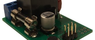
I assembled this programmer five years ago on a board made from a marker. This is what its printed circuit board looked like after tinning at the assembly stage in the case:
Sorry for the blue electrical tape)), back then, 5 years ago, heat-shrinkable tubing was a novelty.
The programmer cable connector at the other end was cut off, and the cable wires were soldered directly into the board. The cable itself was secured with a metal clamp. The photo shows that the cable is thick, and if it were not secured, bending could disrupt the contact of the wires on the programmer board
To connect to the microcontroller installed for flashing on a solderless breadboard, I used colored flexible wires. Connected with wires of the same color, taken from the twisted pair wires. This is done so that, on the one hand, the wires do not break during operation, and on the other, easy connection to the breadboard is ensured. The length of these wires should be a maximum of 20 - 25 cm, in order to avoid errors from interference during programming. Do not use ordinary unshielded wires instead of a COM cable! You will be tormented by errors when installing the firmware.
The programmable microcontroller requires an external +5 Volt power supply supplied to the programmer. For this purpose, you can assemble a stabilizer on a 7805 chip, powered by an external power supply, or do it simpler and use a cable and charger with a USB output, soldering the USB cable wires directly to the printed circuit board.
For reference: power and ground in the USB connector go along the edges. Here is the pinout of the USB connector:
Theoretically, if you are a fairly careful person, you can also get power from the USB port of your computer by connecting this cable to it, but remember, you do this at your own peril and risk! It’s better to find money once and buy a USB charger. Do not use non-USB, unstabilized chargers for cell phones and other equipment; you risk damaging the microcontroller.
When powered from the computer's USB port, if the wires of the programmer +5 volts (VCC) and ground (GND) are shorted, you risk burning the south bridge of the computer's motherboard; repairing such a motherboard will be impractical. I used both options to supply power, both through the stabilizer and through the cable from the USB charger. One more nuance, after programming the microcontroller, in order for the microcontroller to start, it is necessary to break the RESET circuit.
This can be done simply by unplugging the wire connected to the RESET pin of the programmer. And then the program embedded in the microcontroller will begin to execute. I decided to make a more convenient solution and installed a small-sized key switch to break the RESET circuit.
In other words, when it is turned off, the current no longer flows in this circuit and the microcontroller starts working. Instead of a key switch, you can use any small-sized button with a lock, or install a toggle switch. Whose imagination will tell you what?
Surely you have already noticed that on the diagram of Gromov’s programmer there are some unfamiliar words, in particular VCC, GND, MISO, MOSI, SCK and RESET. Let's look at what these designations mean using the Attiny 2313 microcontroller as an example.
In this case, a very common and inexpensive microcircuit is shown: the AVR Tiny microcontroller (aka Attiny) 2313. The legs of the microcircuit, as we can see, have their own number. The numbering goes counterclockwise, from the key in the form of a dot located in the upper left corner of the microcontroller case. The figure below is an example of how the numbering works on microcircuits in a DIP package:
We are primarily interested in the six legs listed above. We will briefly touch on the purposes of all the others at the end of the article.
So, let's decipher:
VCC. We supply the supply voltage to the microcircuit to this leg. The standard is 5 Volts. An upward deviation is permissible, up to 5.5 Volts. Voltage above 6 Volts can damage the microcircuit. A smaller deviation is more acceptable. There are versions of Tiny 2313V microcontrollers that can even operate from two AA batteries or rechargeable batteries, or from a voltage of 2.4 Volts.
GND. Well, this is the familiar and well-known “ground”, it is also “mass”, and it is also the minus of power. This contact is common to all devices that are connected to each other. If you connect any device blocks to each other, their lands should be combined. In this case, the microcontroller ground is combined with the programmer ground.
MISO. Abbreviation for M aster – I n – S lave – O ut. This line transmits data from the microcontroller to the programmer.
MOSI. Abbreviation for M aster – O ut – S lave – I n. This line also transmits data from the programmer to the microcontroller.
SCK. A clock signal is generated on this line.
RESET. This pin is used to reset the microcontroller after erasing with a single pulse. If RESET is disabled by mistakenly setting a certain fuse (we will talk about setting this and other fuses in the following articles), we will not be able to erase and reflash the microcontroller via the SPI interface.
It is enough to connect these listed 6 pins of the programmer to the 6 legs of the microcontroller, and we can flash the MK.
Let's look at the rest of the MK legs:
The Tiny2313 microcontroller has 3 ports: A (A0-A2, 3 legs), B (B0-B7, 8 legs) D (D0-D6, 7 legs), in total there are 18 input/output ports used as legs. Each of these pins can be configured separately as input and output. They are not port pins, only ground (GND) and power (VCC).
The additional purpose of some MK legs is discussed below:
OC1A AND OC1B. Legs for generating PWM (Pulse Width Modulation) signal, timer 1.
OC0A and OC0B. Legs for generating a PWM signal, timer 0.
AIN0 and AIN1. Legs for supplying an analog signal to the microcontroller.
XTAL1 and XTAL2. Legs for connecting a quartz resonator for clocking from it.
RXD and TXD. MK connection lines via UART interface.
I hope this article will be useful to novice microcontroller enthusiasts, and will allow you to build a programmer that will delight you with its work for a long time.
Continue reading: How to sew using a Gromov programmer