Turning off the light with a clap: benefits and advantages
The high-tech device closes and opens an electrical circuit when a sound signal is given, such as clapping your hands. It is capable of remotely controlling not only the lights in the house, but also other electrical appliances: a fan, a humidifier, a stereo system, equipment, and aquarium lighting.
This useful device replaces or duplicates the traditional switch/remote control, saving users time on actions. All electrical consumers located in the acoustic sensitivity zone of the device can be equipped with acoustic switches.
In a transistor housing
The switch in a transistor housing is placed in a plastic box with a degree of protection from dust and moisture ≥ IP30.
Transistor devices are successfully localized in low-current networks (alarms, video surveillance, etc.).
Without housing
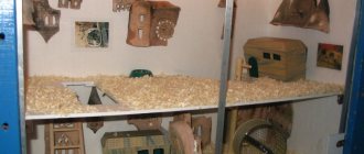
The use of a product without a housing is justified if the user intends to integrate the product into the housing of some electrical appliance. For example, it involves fixing a printed circuit board with components and an acoustic sensor under the air conditioner casing or in a fan stand. An open assembly is more compact and noticeably cheaper than a device in a case.
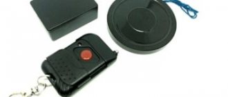
Switches and lamps "plug-socket"
A plug-socket switch is a removable electrical installation product in a plastic case with an input plug for connection to the network. The product is equipped with 1-3 output sockets for connecting floor lamps, sconces, complex household appliances, equipment, gadgets and other energy consumers. The product is an adapter for the path of electric current from a 220 V network to the load, equipped with a sound control board.
It’s very easy to insert 1–4 switches into the room’s fixed sockets and configure them for different consumers (or groups of consumers for devices with “double” or “tee” type outputs). For example, the 1st switch will connect↔disconnect the power socket with 3 claps, the 2nd will operate with 4 claps, the 3rd will respond with 5 claps, the 4th will control 6 claps.
The acoustic switch built into the “plug-socket” is triggered by clapping your hands thanks to selective filtering, highlighting characteristic sounds from background noise.
Acoustic device test
The acoustic sensor for turning the light on and off is tested for the likelihood of activation from any sharp sounds and noises, except pops. As an experimental device, we will consider the domestically produced Claps Max switch. Let's check whether it will respond to sounds - from a hammer hitting a board, a switched-on impact wrench, a jigsaw and grinder, or the clicking of a screwdriver on metal. Such sounds may trigger the activation of the device.
Video: testing the Claps Max acoustic switch
In our version, the device did not respond to the sound of power tools turned on, nor to the sound of a hammer, nor to the clicking sound of a screwdriver. At the same time, it continued to respond to clapping its hands. This can be called an excellent result.
Self-assembly and installation of an acoustic (or cotton) switch should be carried out in compliance with safety standards. After testing the device for susceptibility, you can make adjustments to its settings.
In recent years, remote lighting control systems have gained popularity. Sound commands are accepted by the clap switch. When the clap is strong enough, the light turns on or off. The device can be purchased at a store or, if you have sufficient knowledge of the basics of electrical engineering, you can make it yourself.
Application: relevance
A cotton switch is indispensable in cluttered (with poor natural light) rooms where it is difficult to get to or find electrical fittings on the wall.
Sound devices are especially in demand when organizing lighting/equipping electrical control systems for various storage facilities, warehouses and utility rooms.
Acoustic switches in residential areas
Sound devices are installed in the basements of buildings, vestibules and storage rooms of private houses/apartments. The remote control is useful in a children's room: in order to turn off the lights, children no longer need to move a chair or ask their parents for help. A cotton switch is indispensable for people with disabilities: there will be no need to resort to the services of relatives.
How does an acoustic switch work?
A microphone or acoustic sensor converts sound vibrations into an electrical signal. After the audio frequency amplifier, the AF signal is detected, and a constant voltage is supplied to the base of the transistor switch, the load of which includes the relay winding. After exceeding the threshold level on the base, the key is activated and the relay closes the 220 V power contacts of the electrical receiver. When the sound command is repeated, the circuit automatically turns off and the current flow in the lamp or electrical appliance stops.
Specifications
Typical technical characteristics of an acoustic device for use in a residential building:
- net weight (without packaging) 30 – 60 g;
- overall dimensions 40*40*15 –86 *86 *26 mm;
- household voltage 220 V;
- maximum load current 5A;
- load power 200–1100 W;
- sound sensitivity adjustment 20–150 dB;
- housing protection class IP30 – IP34;
- relative humidity from 20% to 60%;
- operating temperature from 0°C to +40°C;
- Product warranty period is 12–24 months.
Components
A standard acoustic switch consists of the following parts, soldered on a printed circuit board:
- transistors and diodes;
- diode bridge and zener diode;
- trigger and comparator microcircuits;
- resistors and capacitors;
- microphone and relay.
The board fits into a sturdy plastic case with latches.
Differences between clap and sound (voice) switch
Voice control devices are more complex than slam switches. They use special active filters on microcircuits that perform the functions of a command decoder. They recognize a sequence of vowel sounds of a certain frequency and duration, ignoring acoustic interference.
Test procedure for cotton switches
After installing and connecting the device, it must be tested under real operating conditions. The test consists of simulating household noises and the reaction of the installed system to them. The following noises can be considered common in the home:
- noise of a household vacuum cleaner;
- electric drill operation;
- the clatter of plates;
- sound from working with a hammer;
- phone calls, etc.
By creating such noise effects one by one, we check which of them the device can respond to. You can try to eliminate unwanted reactions from the device by adjusting the microphone sensitivity. This feature is implemented in all device models.
The production of such a switch is shown in detail in the video.
To make an acoustic switch yourself, you undoubtedly need solid knowledge in the field of radio electronics and electrical engineering, but installing a standard device is within the capabilities of a performer with minimal electrical installation skills. I wish you success!
The question of how to assemble an acoustic switch at home is asked sooner or later by every radio amateur, since such a device for closing an electrical circuit provides great scope for use, ranging from connecting a simple lamp to use in complex security systems and a “smart” home.
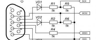
Connection diagram and DIY installation
The electrical connection diagram for a cotton switch is no different from the connection diagram for a single-key switch. Only in series (or instead) the clapper switch is switched on in the open circuit.
Step-by-step instruction
The acoustic module itself is glued with tape from the inside to the chandelier or the body of an electrical appliance; connections are easier to make with Wago-type terminal blocks:
- de-energize the network, break the power circuit going to the key switch, remove the insulation and strip the ends of the wire;
- a pair of white wires from the acoustic module are connected to the phase and neutral coming from the shield or junction box;
- The two remaining black wires are similarly connected to the terminals of a lamp or household appliance.
All that remains is to move the button of the conventional switch to the “on” position, the system is ready for operation.
Adviсe
When choosing a remote switch with an acoustic sensor, you should pay attention to the design features of the device. The presence of a built-in power supply will eliminate further costs of purchasing a low-voltage DC source or batteries.
Please note that dimmer switches are only used with the type of load for which they are designed. For example, devices based on triacs do not “mate” with energy-saving and LED lamps.
Principle of operation
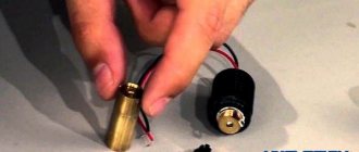
A primitive model of an acoustic device that can be assembled by hanging installation with a test light and an 8-volt power source. The following are used:
- powerful direct bipolar transistor type KT818, or foreign analogues,
- push-pull microphone amplifier,
- a regular microphone (for example, from a tape recorder or headphones)
Such an acoustic switch device allows you to clearly trace the mechanism of converting a noise signal into an electrical one. The microphone receives the wave signal and transmits it to the amplifiers, after which a transistor is triggered through the base of the switch, starting the current connection.
Acoustic switch - switch - Do it yourself
The best acoustic switch.
Author: Vladislav Myasin Published 08/20/2010
Many of you have had to fumble for a long time in the dark for the switch of a table lamp, bumping into various objects. This process is usually accompanied by noise and obscene language. But now this has come to an end! The proposed acoustic switch compares favorably with all similar ones: it does not require an external power source, is assembled from common parts (in particular, it does not have a relay), has good sensitivity and protection from network interference, and most importantly, simplicity of design and configuration. Clap your hands and the device will turn on the light, another clap will turn it off. The time spent in each state is unlimited.
Operating principle
The sound signal from the electret microphone is fed to a double amplifier stage using transistors VT1 and VT2. The use of transistors of different conductivities made it possible to avoid parasitic connections. Capacitor C3 protects the circuit from network interference. Resistor R5 bypasses pin 11 of the microcircuit and at the same time acts as a load for transistor VT2. The signal at the output of the amplifier has a sinusoidal shape, but to control the trigger, the signal must be pulsed. Signal conversion is carried out by a single-vibrator made on the DD1.1 block of the K561TM2 microcircuit. The pulse duration at the indicated R6 C4 ratings is 0.5 s.
The heart of the device is a trigger made on the DD1.2 element of the same microcircuit. A trigger is a device that has two stable states and switches from one equilibrium state to another whenever an external control signal is applied. When there is a low voltage level at the output of the trigger (pin 1 of the microcircuit), transistor VT3 is closed and the load is de-energized. At a high logic level at the DD1 output, the transistor VT3 and the thyristor (respectively) are in the open state and the load (EL1) is supplied with supply voltage. The device can only be used with an incandescent lamp, because The load is supplied with a voltage rectified by four diodes connected in a bridge circuit. The power supply is made according to a transformerless circuit. The alternating voltage is rectified by the diode bridge VD2-VD4, passes through the limiting resistor R9 and is filtered by the zener diode VD1 and capacitor C5. If the resistance R9 is too high, the current may not be enough to unlock the thyristor; if it is too low, the zener diode will burn out. The optimal value for R9 is 28 kOhm. The sensitivity of the device to cotton is 4-6 meters. Details
The ELI incandescent lamp is designed for a voltage of 220-235 V and a power of 7-60 W.
Any electret microphone. All fixed resistors are MLT type, the power of resistor R9 is 2W. All capacitors have a voltage of at least 16V. Zener diode VD1 is replaced by KS 175A, D808, D814A or a similar one with a stabilization voltage of 9-12 V. Rectifier diodes VD2-VD4 are replaced by diodes KD226V, KD258B, D112-16 and similar, taking into account that their reverse voltage should not be less than 300 V. Instead of discrete diodes, you can use a ready-made rectifier bridge such as KTs402A, KTs405A, KTs407A. Instead of the VT3 transistor, you can use KT940A-KT940G, KT630A-KT630V and even KT315B. Transistor VT1 of npn structure, VT2 of pnp structure. Thyristor VS1 must have a minimum control electrode current. In addition to what is indicated in the diagram, it can be T112-16-x or another, with worse characteristics, for example, type KU201 K-KU201M, KU202K-KU202N. Installation
The device is assembled on a circuit board and secured in a housing made of dielectric material. Observe the pinout of the microcircuit!
Assembly option
The circuit of a simple acoustic switch with a power supply of 4.5-12 volts, and with an operating range at a distance of 2-3 m, is assembled on a printed circuit board or breadboard and consists of a larger number of parts.
Such devices are also called “clap” devices; their functional feature is sequential switching off and switching off with a sharp sound signal, similar to the clapping of palms.
The KT818 transistor connected to a relay with a 9-volt power coil is responsible for the power part.
The sensitivity of the electret microphone is set by a 10 kOhm power resistor and a 0.1 μF capacitor. It can be adjusted based on the resistance of the resistor and the capacitance of the capacitor, and through the use of more sensitive transistors. The resistor value can start from 2 kOhm, depending on the power supplied to the circuit.
Next are two amplification stages with bipolar transistors KT315 (you can use imported analogues, for example 2N5551). Resistance values can be varied by 50%. For an electromagnetic relay, you need to install a protective diode. Silicon 1N4148 or 1N401 is suitable for this function. To indicate the operation of the circuit, an LED can be installed in the power section.
As you can judge from the photo, homemade acoustic switches are quite compact, it is easy to pick up a case for them and use them in mobile and static devices; they are powered by ordinary batteries. You can also use mobile phone chargers with an output voltage of 5 volts.
When testing, you need to pay attention to the reaction of the device, since to start and turn off a properly assembled acoustic switch you need to make a clear and sharp clap.
Effective when demonstrated, the response to more vague and washed-out noises can significantly impede the use of the device, causing involuntary switching on or off during background noise. It is also important to provide the most optimal microphone location.
To manufacture built-in sound sensors, you can use circuits with a 220-volt power supply, which can be mounted with standard key switches for lighting devices. They are used in which thyristor triggers and key mechanisms are used.
The transistor trigger is powered by a diode and a resistor. The circuit includes voltage equalizers. The complicated circuit provides for the presence of a comparator - an additional zone that cuts off interference and improves the quality of operation of the switch.
DIY acoustic switch
An acoustic switch is a very useful and necessary thing in the household, especially if you want to automate some devices or lighting in your home and add creativity to your home! Using an acoustic switch, you can turn the lighting off and on or use it for other devices, such as an electric kettle or fan.
This scheme is fully operational, streamlined and stable. There are many diagrams of similar devices on the Internet, but when assembling them, a lot of performance problems arise and some of them lead to long discussions at the end of which, the problem is often not solved. Below is the diagram itself.
The circuit is powered by a voltage of 5 to 9 volts, so choosing a power source will not be difficult. You can use, for example, a crown or other batteries and accumulators. If you need stationary power, then there are many power supply circuits online, even a transformerless one will do.
The printed circuit board is made for DIP components, but despite this, it has quite compact dimensions and choosing a housing for it will not be difficult. You can download the printed circuit board from the link: