DIY car battery charger - is it possible? How to do it and what needs to be taken into account is further in the article. Do-it-yourself charger for a car battery: 3 stages of calculations
Every novice radio amateur is able to create such a necessary device as a charger. The entire operation of a car depends on its on-board system, which draws strength and energy from the battery. But the battery is not suitable for generating electricity. It is most likely a kind of energy storage. At the right moment, energy is supplied to operate the vehicle, but is not replenished. Of course, the generator helps to restore a small part of the energy given, but this is very little for complete restoration. Therefore, a charger is used.
Making a charger with your own hands
Of course, the entire power generation system in a car was made by smart people. Under normal operating conditions, it can last for many years without recharging. In this case, the car battery charger may not be useful for a very long time. The trio of generator, regulator and battery works very well and powers the entire system.
The essence of the functioning of any charger is that this device allows you to convert voltage from a 220-volt household network into the voltage necessary to charge the battery
Of course, this is only in ideal theory. In ordinary life, anything can happen. From sudden changes in temperature that negatively affect the operation of the car, to the possibility of stopping the use of the car for a very long time.
There are a lot of different options for possible waste of battery life: the battery itself has already completely exhausted its service life and does not hold electricity at all, the battery cannot be evenly and correctly loaded and charged during a short trip with the engine frequently turned on and off, a large number of connected devices and a faulty generator . All these reasons do not allow the battery to be fully charged or quite soon it is discharged.
Later, a situation may arise when the car refuses to start, the battery is discharged and there is no place to recharge it. In such a situation, a homemade charging device is suitable. Or a homemade recharger, abbreviated as battery charging. The simplest circuit for a car battery charger: a circuit consisting of a semiconductor diode and a light bulb. You can literally make it from things that are at hand. The current source is an electricity network of 220 Volts. The diode can change alternating current to direct current, and the light bulb limits the current.
Calculation of a simple charger:
- The current can be determined by dividing the lamp power number by the network voltage;
- If the lamp power is 60 W, then the ammeter will show a current of 0.27;
- The diode will cut off the second part of the sine wave graph, and the actual current will be 0.32 A.
Thus, connecting this charger will not be more difficult than assembling it. When the car does not start, it is these simple schemes that help get out of the current situation. It is important to remember that such a device cannot be connected to a car battery without first removing it from its workplace. This can cause big problems and automatic damage to the entire vehicle system. There are special batteries for batteries: JRMB45 and IBL. They are sold in many electronics stores.
Converter from UPS.
Recently, very often people come to me with a request to provide instructions for converting a UPS (UPS) into a car voltage converter from 12 to 220 volts, and in this article I will try to explain how this can be implemented.
In fact, the UPS uninterruptible power supply can be used in a car as a voltage converter without any modifications, since the UPS itself is an inverter, which is designed to receive 220 Volts from a built-in 12 Volt lead battery.
In particular, the UPS uses lead batteries with a capacity of 7 or 10 Amp hours; in some powerful uninterruptible power supplies you can find two or even 4 similar batteries, which are connected in parallel to increase the capacity and battery life.
To remake the uninterruptible power supply, you first need to disassemble and remove the built-in battery. The power buses that are connected to the batteries must be removed from under the housing. It is advisable to use wires with an effective cross-section of 12 sq. mm. In many uninterruptible power supply systems, the housings are made of plastic, so you can simply drill the housing and remove the wires. It is advisable to connect the uninterruptible power supply directly to the car battery - the plus from the uninterruptible power supply to the plus of the battery, and the minus, respectively, to the minus.
What can be connected to a UPS?
First of all, pay attention to the power of the uninterruptible power supply. Cheap Chinese uninterruptible power supplies with a price of no more than 2000 rubles provide a relatively low output power. In my practice, I repaired power supply units from 300 to 1100 watts, but ideally they did not provide the declared power. For example, a Chinese 650-watt uninterruptible power supply could not handle a real load of 300 watts. It is necessary to test the power of an uninterruptible power supply specifically for passive loads - heaters, incandescent lamps, etc.
Another drawback is the shape of the output voltage, which differs from the mains sine wave. Almost all uninterruptible power supplies have a modified sinusoidal output. This form of voltage is not the best option, but it is possible to power motors and other loads, although I do not recommend connecting mains transformers and asynchronous motors to the UPS for a long time. Large size and weight can also be considered a disadvantage, taking into account the fact that modern automotive voltage converters using pulse circuits have a weight and size much smaller than uninterruptible power supplies.
But nevertheless, if you need a pretty good, cheap inverter for use in field conditions, a UPS can be considered the best option and, in addition, uninterruptible power supplies have protection against overload and short circuits at the output.
AKA KASIAN.
Battery charging circuit: capacitor model and assembly in stages
Another charger is a device made using a capacitor circuit. The electrical circuit has a great useful effect and does not emit heat into the external environment. This allows you to have constant current, short circuit protection and do all the work yourself.
Today there are many types of chargers, but any device is based on two main components - a transformer device and a rectifier
- In any case, the first stage of assembly is to select a circuit, for example 250. In this section - a capacitor circuit.
- The second and important point is the choice of housing for the charger. The most suitable case may be a milliammeter; everything needs to be removed from it, leaving only a pointer element that will help show the result.
- The transformers are fastened with screw elements on an aluminum plate.
- Voltage regulating devices are located on top of the housing. Install special terminals that help output voltage to the terminals.
- All elements of the charger are located inside the case.
- Connect all elements to each other according to the diagram.
Diodes and capacitors are also necessary in this circuit; they are the main element of any charger, regardless of the type of circuit. The question often arises as to what diodes are needed. Diodes with a current intake of about ten amperes are selected.
Efficiency increases as the circuit becomes more complex. This will allow you to work in different modes.
One of the most selected modes is automatic. The automatic machine allows you to eliminate constant monitoring, increase the service class of the device and, accordingly, the price of the product itself or its components.
Laboratory power supply from UPS
In the article, the author tells how to make a laboratory power supply needed in amateur radio practice from a faulty or outdated uninterruptible power supply.
The main purpose of uninterruptible power supplies (UPS) is short-term power supply to various office equipment (primarily computers) in emergency situations when there is no mains voltage. The UPS includes a battery (usually 12 V), a step-up voltage converter and a control unit. In standby mode, the battery is recharged, in emergency mode, the voltage converter is turned on.
Like all equipment, UPSs fail or become obsolete. Therefore, they can be used as a basis for the manufacture, for example, of a laboratory power supply unit (PSU). The most suitable for this may be UPSs in which voltage converters operate at low frequencies (50...60 Hz), and they include a powerful step-up transformer, which can also work as a step-down transformer.
To manufacture a laboratory power supply, the KIN-325A UPS was used as a “donor”. During development, the task was to obtain a simple circuit, using as many elements as possible from the “donor”. In addition to the transformer and housing, powerful field-effect transistors, rectifier diodes, a quad op-amp microcircuit, an electromagnetic relay, all LEDs, a varistor, some connectors, as well as oxide and ceramic capacitors were used.
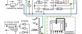
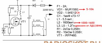
The power supply circuit is shown in Fig. 1. The mains voltage is supplied to the primary winding of transformer T1 (marked RT-425B) through fuse link FU1 and power switch SA1. Varistor RU1, connected in parallel to this winding, together with the fuse link, protects the power supply from increased mains voltage. Through the current-limiting resistor R1 and the diode VD1, the LED HL1 is powered, signaling the presence of mains voltage.
Rice. 1.
A powerful rectifier on diode assemblies VD2-VD5 is connected to winding II (with a tap in the middle, rated voltage 16 V) of transformer T1. Depending on the position of the contacts of relay K1.1, the rectifier operates as a full-wave rectifier with a common terminal of the transformer (shown in Fig. 1) and an output voltage of about 10 V, or as a bridge with an output voltage of about 20 V. The output voltage of this rectifier is supplied to the regulating element - field transistor
VT1. Capacitors C1 and C3 smooth out the ripples of the rectified voltage, resistor R2 is a current sensor. Resistor R17 ensures the minimum load of the voltage stabilizer in the absence of external load.
The low-power rectifier is assembled using diodes VD6-VD9 and smoothing capacitors C2 and C5. It powers the parallel voltage regulator on the DA1 chip, op-amp DA2, relay K1 and fan M1. The HL2 LED signals the presence of voltage at the output of this rectifier.
An adjustable voltage stabilizer is assembled on op-amp DA2.3 and transistor VT1. The reference voltage to the voltage regulator - resistor R11 - comes from the output of the stabilizer on the DA1 chip. The output voltage of the power supply from the engine of the trimming resistor R12 is supplied to the inverting input of the op-amp DA2.3. This resistor sets the maximum output voltage. The adjustable current limiter is assembled on op-amps DA2.1 and DA2.2. A voltage proportional to the output current from the sensor - resistor R2, is supplied to the voltage amplifier at the op-amp DA2.1 and then to the op-amp DA2.2, which compares it with the standard one supplied to its non-inverting input from the output of the resistive divider R4R7R8. Resistors R7 and R8 set the current limiting threshold.
Transistor VT2 controls relay K1. It will work when the voltage at the gate of this transistor exceeds the threshold value (for the transistor indicated on the diagram, the threshold voltage is 2...4 V). Trimmer resistor R19 sets the output voltage of the power supply unit, above which the relay switches the output voltage of the rectifier. Transistor VT3 together with thermistor RK1 controls fan M1. It turns on when the temperature of the heat sink on which the VT1 transistor and thermistor are installed exceeds a preset value. The threshold temperature is set by resistor R15. The thermistor supply voltage is stabilized by a VD11R16 parametric stabilizer. The excess supply voltage of relay K1 drops through resistor R13, and fan M1 - through resistor R18.
If the load current does not exceed the threshold value, the voltage at the non-inverting input of op-amp DA2.2 is greater than the voltage at the inverting one, at its output there is a voltage close to the supply voltage, therefore the VD10 diode is closed, and no current flows through the HL3 LED. In this case, the control voltage to the gate of the field-effect transistor VT1 is supplied from the output of the op-amp DA2.3 through resistor R14 and the voltage stabilizer operates. If the output voltage of the stabilizer is less than 4 V, transistor VT2 is closed and relay K1 is de-energized. In this case, the voltage at the drain of transistor VT1 is 10 V. When the output voltage is more than 4 V, transistor VT2 opens and relay K1 is activated. As a result, the voltage at the drain of transistor VT1 increases to 20 V. This technical solution makes it possible to increase the efficiency of the device.
When the load current exceeds the threshold value, the voltage at the output of op-amp DA2.2 will decrease, diode VD10 will open and the voltage at the gate of transistor VT1 will decrease to a value that ensures the flow of the set current. In this mode, current flows through the HL3 LED, and it signals the transition to current limiting mode. The limiting current is set by resistor R8 in the range of 0...0.5 A and R7 in the range of 0...5 A. Capacitors C4 and C6 ensure stable operation of the current limiter. Increasing their capacity increases stability, but reduces the performance of the current limiter.
The device uses fixed resistors - S2-23, P1-4 or imported ones, tuning resistors - SP3-19, variable resistors - SP4-1, SPO. In order for the scale of variable resistors that regulate voltage or current to be linear, they must be of group A. Thermistor - MMT-1. Resistor R2 is made from a piece of PEV-2 0.4 wire, 150 mm long. In addition to the function of a current sensor, it also works as a fuse in case of emergency situations. Oxide capacitors are imported; instead of non-polar ones, you can use ceramic K10-17. The fan is a computer fan with a current consumption of 100...150 mA, its width should be equal to the width of the heat sink. Relay - any, designed for a switching current of 10 A and a rated winding voltage of 12...15 V. XS2, XS3 - sockets or terminal blocks.
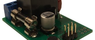
Most of the elements are placed on two printed circuit boards made of fiberglass foil on one side with a thickness of 1.5...2 mm. On the first (Fig. 2) rectifiers are assembled, transistors VT2, VT3 with their “surrounding” elements and some other parts are mounted. The printed conductors connecting the elements of a powerful rectifier are “reinforced” - pieces of tinned copper wire with a diameter of 1 mm are soldered onto them. The “standard” terminals of the T1 transformer are wired; they are equipped with two sockets. If you plan to use them, the corresponding plugs are mounted on the first board, which are unsoldered from the “native” UPS board.
Rice. 2.
The second board (Fig. 3) contains all the microcircuits, LEDs, and some other elements. On the side free from printed conductors, push-button switch SA1 (P2K or similar) is glued. The LEDs must fit into the “standard” holes on the front wall of the case, and a “standard” pusher is glued to the switch.
Rice. 3.
The first board is installed next to the rear wall of the case, the second - close to the front. To fasten the boards, two screws and “standard” mounting plastic stands on the top cover of the case are used. A VT1 transistor, a thermistor and a fan are placed on a finned heat sink with external dimensions of 30x60x90 mm (it is installed between the boards). Heat shrink tubing is placed over the thermistor and then glued to the heat sink next to the transistor. Since when the temperature of the thermistor changes, the field-effect transistor VT3 opens and closes smoothly, the fan begins to rotate and stops also smoothly. Therefore, transistor VT3 can noticeably warm up and cannot be replaced with a low-power one, for example 2N7000.
On the front panel (Fig. 4), variable resistors and connectors XS2 and XS3 are installed in the holes, to which resistor R17 and capacitor C7 are soldered. The block plug XP1 and socket XS1 are “native”, they are located on the rear wall in its lower part. The XS1 socket can be used to connect any device that operates simultaneously with a laboratory power supply, such as an oscilloscope.
Rice. 4.
The setup begins by setting the maximum output voltage. This is done using resistor R12, the slider of resistor R11 should be in the upper position in the diagram. If you do not plan to build a voltmeter into the power supply, resistor R11 is equipped with a handle with a pointer and its scale is calibrated. When transistor VT2 is open, by selecting resistor R13, the rated voltage is set on relay K1, and when VT3 is open, resistor R18 is used to set the voltage to 12 V on fan M1. The fan switch-on temperature is set with resistor R15.
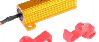
To set up a current limiter, a series-connected ammeter and a load variable resistor with a resistance of 10...15 Ohms and a power of 50 W are connected to the power supply output. The resistor sliders R4 and R7 are set to the left position according to the diagram, the slider R8 is set to the right. The load resistor should have maximum resistance. When the output voltage is about 10 V, the load resistor sets the current to 5 A, and resistor R5 sets the voltage to 0.9...1 V at the output of op-amp DA2.1. Using a load resistor, increase the output load current to 6 A and, by smoothly rotating the slider of resistor R4, turn on LED HL3 (turn on the current limiting mode) and then set the output current to 5 A with resistor R4. When moving the slider of resistor R7 to the right (according to the diagram), the output the current should decrease to zero. In this case, resistor R8 can be used to regulate the output current in the range 0...0.5 A.
If you do not plan to build an ammeter into the power supply, the scales of these resistors are calibrated. To do this (in current limiting mode), the output voltage and load resistance are changed, the required current value is set and marks are placed on the scale. In this case, in the range of 0...0.5 A, the current is set by resistor R8 (resistor R7 should be in position “0”), and in the range of 0...5 A - by resistor R7 (resistor R8 should be in position “0”).
In current limit mode, you can charge batteries and rechargeable batteries. To do this, set the final voltage and charging current, and then connect the battery (battery).
A further direction for refining the proposed power supply is the installation of a built-in digital voltmeter, ammeter or combined measuring device.
Author: I. Nechaev, Moscow
A competent homemade charger: what is important to remember
Before you connect the charger to your car battery, you need to know all the safety precautions and precautions. They cannot be neglected.
- Do not confuse plus and minus after connecting the battery.
- It is impossible to check the operation of the entire system using the “old-fashioned method” - a short circuit.
- The charger must not draw any current during connection and disconnection.
- Compliance with fire safety rules.
- The device must be supervised while it is turned on.
- The power supply must be capable of connecting a battery.
Any homemade charger should not be used to charge a very discharged battery. This can permanently damage the system. Many chargers have a light bulb in their design. When charging a battery, the current can be very high, so if the battery is very discharged, the light bulb is removed after the current decreases. This reduction means further charging of the battery with control of current and voltage.
The current decreases, and the voltage in the terminals, on the contrary, increases. When the voltage reaches 12 V, charging is complete. If you overuse the charger, certain parts of the battery may melt and fail, rendering the entire battery unusable.
How to charge a battery: pulse model
Such devices are divided into charging and charging-starting products. Charging products perform their work using the network. Automatic charging of the charging and starting product is performed autonomously and does not depend at all on the location of the vehicle itself.
Pulse chargers are convenient and easy to use. They have a lot of advantages, thanks to which they are loved by car owners from all over the world.
The first option is convenient for charging the car in the garage and it has electricity. The second case allows you to charge the battery in an open field, knee-deep in snow.
These two types of charging come in two types according to the principle of operation: pulse and transformer. Pulse ones can interact with high current while having small dimensions. Transformer chargers are large machines that take up a lot of space and are difficult to use on the road.
What to use for a 10V pulse charger:
- Use a step-down transformer in the circuit;
- Use a powerful magnetic wire;
- Use insulators;
- Install regulators and modulators;
The voltage indicator, thanks to the entire system, can be adjusted. In such a charger, it is necessary to take into account the capabilities of the battery of the car itself.
Original DIY battery charger: advantages and disadvantages
In addition to mobility and size, a charger such as a pulse charging element has its advantages and disadvantages. Soviet charging devices, such as Kedr or Orion, are quite cheap and very easy to buy. But assembling a car charger for a car or scooter at home is more difficult. It is important to take into account all the characteristics of each part and the harmonious operation of the entire system together. You can’t just take and wind wires around batteries; you need knowledge of electromechanical systems and circuits.
Pulse chargers are divided into manual, automatic and semi-automatic. They work in two directions and have special modes.
Pros of a pulse charger:
- Good protective system;
- Helps increase battery life;
- Low price for the entire assembly.
An important disadvantage is the complexity of the design. This can be avoided by self-assembly.
Methods: how to connect an ammeter to a charger
An ammeter can give a complete picture of the condition of the battery. For example, many chargers are equipped with lights that will not indicate the voltage or charging current, or a fault in the circuit.
If you wish and have a little amateur radio experience, you can make a car charger yourself
How is the ammeter connected?:
- The frog leg is connected to the wire connecting the generator and the battery;
- Eliminates the possibility of wire overheating;
- When the ammeter is operating, slight heating of the device itself is allowed.
By connecting an ammeter to the UPS, you can take the results and monitor the proper operation of the engine battery and charger.
Converting an uninterruptible power supply for charging
In this case, a minimal transformation similar to that described in the paragraph above is not needed. After all, the uninterruptible power supply has its own battery, which is charged as needed. As a result, to turn the UPS into a charger you need to do the following:
- Locate the primary and secondary circuit of the transformer. This process is described in the paragraph above.
Supply 220 volts to the primary circuit by inserting a voltage regulator into the circuit - as such, you can use a rheostat for light bulbs, replacing a traditional switch.
The regulator will help calibrate the voltage on the output winding in the range from 0 to 14-15 volts. The place where the regulator is inserted is in front of the primary winding.
Connect a 40-50 ampere diode bridge to the secondary winding of the transformer.
Connect the terminals of the diode bridge to the corresponding poles of the battery.
The battery charge level is monitored by its indicator or voltmeter.
Write a letter
For any question you can use this form.
Many PC users have old UPSs that have expired. A common cause of disability is battery failure. Since replacing with new batteries is unprofitable, and sometimes simply impossible due to the lack of analogues, these devices are simply lying around idle or thrown into the trash.
But you can give a second life to the UPS by making it a very useful device - an inverter that converts 12V in the car’s on-board network into the 220V required for some devices. Despite the fact that the factory version of the inverter will cost a lot of money, this way you will save money and make the right thing out of trash.
So, the first thing to do is remove the old, leaking batteries. They can be easily dismantled by removing the bottom cover and disconnecting the power wires. If there are traces of leaked electrolyte, clean the case from oxidation crystals.
This operation will ensure the elimination of further acid leakage and will also significantly lighten the weight of the apparatus.