High voltage voltage source for smokehouse
Greetings, homemade radio amateurs, as well as all lovers of home-made smoked products!
Very often, when assembling homemade smoking installations, people wonder where to get the high voltage source that is necessary to create a static field in the smokehouse? Buying ready-made high-voltage generators is unreasonably expensive, especially since this is a rather specific product and is not sold on every corner. Many also believe that such a high-voltage source is inextricably linked with great risk, because if 220V from an outlet is life-threatening, then what can we say about the tens of kilovolts required for good smoking. In fact, speaking about safety, it is worth mentioning that it is the current passing through a person that is dangerous to life, and not the voltage, that is, you can even catch electrical discharges with your hands and not even feel them - but only if the high-voltage source does not has high power and, accordingly, cannot produce high current, which is critical for health. For smoking, the main thing is to create a static field; the high-voltage source will essentially operate idle, without load, which means it does not require high power, which could lead to injury when assembling or using the device. There is also a misconception that it is very difficult to assemble such a device with your own hands, since you must be able to read electrical circuit diagrams and have good soldering skills in order to make a board and be able to assemble an electronic circuit on it. In fact, a 10-20 kV high-voltage unit can be assembled without assembling the circuits yourself, but using only a few ready-made modules. As a high-voltage transformer, a part that will directly generate high voltage, you can use a car's ignition coil. In this article, let's look in more detail at how to assemble a high-voltage unit with your own hands, which can be used not only for a smokehouse, but also for various high-voltage experiments, for example, to obtain an interesting effect - Jacob's ladder.
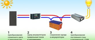
First of all, let's briefly consider the general structural diagram of the device, what blocks it will consist of, and which block will play which role.
The device will be powered from a 220V outlet; contacts for connecting to 220V are shown on the leftmost part of the diagram. Next comes the power supply, which creates the required voltage to power the device - yes, it seems somewhat illogical that the mains voltage is first reduced by an entire order of magnitude, so that then it will be possible to obtain the required 10-20 kV from it, but this is precisely the principle of operation of the device. After the power supply comes an ammeter-voltmeter, which will show the voltage and current consumed by the device. By controlling the current, it will be possible to control the power of the smokehouse. After the ammeter-voltmeter, the supply voltage is supplied to the PWM regulator, the task of which is to create rectangular pulses from which the ignition coil will be powered, as well as to regulate power. The signal from the PWM controller goes directly to the primary winding of the ignition coil - and the high voltage is removed from its secondary winding. It must be remembered that the static field required for smoking is created only by direct voltage, and an alternating voltage is removed from the output of the coil, so a multiplier is connected to the output of the coil. It not only rectifies the alternating voltage, but also increases its amplitude, that is, the voltage, several times, which allows you to achieve the required 10-20 kV, or even 30, depending on the coil used and the voltage of the power supply. To build a multiplier, you will need only 3 high-voltage diodes and three capacitors - these parts are not in short supply, in addition, connecting them will not even require a printed circuit board; the entire assembly will be surface-mounted. Let us consider in more detail below each individual block of the diagram presented above. As a power supply, you can use any power source with an output voltage of 12-16V, and the higher the voltage, the greater the voltage can be removed from the output of the coil. An ideal power supply would be, for example, a computer power supply or a laptop power supply. You also need to pay attention to the power - it should not be too small, because the circuit will consume a current of about 2-3A at maximum power, accordingly, the power supply must have a current reserve. Or you can use a powerful transformer with a 12-14V secondary winding, placing a diode bridge and a smoothing capacitor after it.
After the power supply, the diagram contains an ammeter combined with a voltmeter - this part is not mandatory, the circuit will work without it, but it will not be superfluous to see the supply voltage and the current flowing at the moment. In addition, the circuit provides for power regulation, and the power can be monitored precisely by the ammeter readings; the greater the current, the greater the power, and, accordingly, the voltage at the output of the high-voltage unit. Here you can use, for example, arrow heads, they will provide the best clarity of readings, or built-in devices, as in the picture below, they will not take up much space in the body of the future device.
After the current flow is measured by an ammeter and the voltage by a voltmeter, the supply voltage is supplied to the PWM regulator, perhaps the most important part of the circuit. You can assemble a PWM regulator circuit yourself, using the popular NE555 timer chip, or using a ready-made module, as in the picture below - the author chose the second option. The PWM regulator has a potentiometer that serves to regulate power; when assembling the device, its handle will need to be brought out of the case, secured together with the board, or by unsoldering the potentiometer and connecting it again to the wires.
You can easily find such modules on Ali - they cost very little there, or in radio parts stores. Please note that the PWM regulator must create pulses with a frequency of no more than 1.5 kHz for the ignition coil to operate correctly. If you assemble a PWM regulator yourself, then you need to initially calculate it for this frequency, and if you use a ready-made module, then you need to change the capacitor in it, marked with an arrow, to a nominal value of 10 nF, its code marking is 103. Initially, most PWM regulators operate at more high ranges so that the frequency does not fall into the audible range, but here, on the contrary, it is necessary to reduce it, this can lead to the circuit or coil squeaking slightly - but this alteration is necessary for the correct operation of the ignition coil. Let's take a closer look at what PWM is and how power is adjusted. A constant voltage is supplied to the input of the module, and rectangular pulses are removed from the output; their appearance can be as in the picture below.
Or maybe like this.
The duty cycle of the pulses changes (depending on the rotation of the potentiometer), which is also the duration, which is also the width of the pulses, which is also the duty cycle. In the first picture, the pulse duration is short, therefore, the power supplied to the coil will be small, but in the second picture, the duration is much longer and corresponds to a fill factor of 50% - in this case, the maximum voltage at the coil output is achieved. If you increase the duty cycle even further, the power will, on the contrary, decrease, and the coil may begin to heat up, so to excite the ignition coils you need to use a duty cycle from 0 to 50%. PWM controllers have found wide application due to their high efficiency, because during operation they hardly heat up.
You can use almost any ignition coil - they are easy to buy, for example, at car wrecking yards. The only selection criterion is that the coil is in good working order and wires can be easily connected to it. The thick red wire coming from the coil is its high-voltage output, the voltage is removed from it.
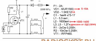
Next, a few words about the multiplier. To build it, you need to use high-voltage diodes rated at least 15,000V - you can find such diodes in a microwave oven, and buy them at a household appliance repair service, where they will be happy to sell them. Capacitors must also be designed for a voltage of at least 15,000V, their capacitance should be approximately 470 pF, the spread of capacitance can be large without losing the functionality of the multiplier. A visual diagram of the connection of diodes and capacitors can be seen in the picture below.
After assembly, the terminals of the diodes and capacitors must be carefully filled with hot glue or epoxy resin to prevent breakdowns between them.
General view of the assembled structure. Before installing it in the case, you can turn it on and test it - if everything is assembled correctly, immediately after turning it on you will hear a characteristic “rustle” created by high voltage - this means the coil and multiplier are working. You can bring the high-voltage outputs close to each other and see small arcs, but you should not short-circuit the high-voltage output.
After this, the structure is assembled in a spacious plastic case, all connections are soldered for greater reliability and protection against short circuits. On the front panel of the case you can place an ammeter-voltmeter, a power regulator and a switch. A high-voltage output is provided on the side or rear of the case, and the supply voltage is also introduced into the case. Despite the fact that the power of the ignition coil is not enough to kill, you should not touch its terminals or the multiplier terminals - it will be very painful. Happy building!
Source
Become the author of the site, publish your own articles, descriptions of homemade products and pay for the text. Read more here.
High-voltage voltage generators with capacitive energy storage
High-voltage, low-power generators are widely used in flaw detection, to power portable charged particle accelerators, X-ray and cathode ray tubes, photomultiplier tubes, and ionizing radiation detectors. In addition, they are also used for electric pulse destruction of solids, production of ultrafine powders, synthesis of new materials, as spark leak detectors, for launching gas-discharge light sources, in electric-discharge diagnostics of materials and products, obtaining gas-discharge photographs using the S. D. Kirlian method , testing the quality of high-voltage insulation. In everyday life, such devices are used as power sources for electronic traps of ultrafine and radioactive dust, electronic ignition systems, for electroeffluvial chandeliers (chandeliers by A. L. Chizhevsky), aeroionizers, medical devices (D'Arsonval, franklization, ultratonotherapy devices ), gas lighters, electric fences, electric stun guns, etc.
Conventionally, we classify as high-voltage generators devices that generate voltages above 1 kV.
The high-voltage pulse generator using a resonant transformer (Fig. 11.1) is made according to the classical scheme using a gas spark gap RB-3.
Capacitor C2 is charged with a pulsating voltage through diode VD1 and resistor R1 to the breakdown voltage of the gas spark gap. As a result of breakdown of the gas gap of the spark gap, the capacitor is discharged onto the primary winding of the transformer, after which the process is repeated. As a result, damped high-voltage pulses with an amplitude of up to 3...20 kV are formed at the output of transformer T1.
To protect the output winding of the transformer from overvoltage, a spark gap made in the form of electrodes with an adjustable air gap is connected in parallel to it.
Rice. 11.1. Circuit of a high-voltage pulse generator using a gas spark gap.
Rice. 11.2. Circuit of a high-voltage pulse generator with voltage doubling.
Transformer T1 of the pulse generator (Fig. 11.1) is made on an open ferrite core M400NN-3 with a diameter of 8 and a length of 100 mm. The primary (low-voltage) winding of the transformer contains 20 turns of 0.75 mm MGShV wire with a winding pitch of 5...6 mm. The secondary winding contains 2400 turns of ordinary winding of PEV-2 wire 0.04 mm. The primary winding is wound on top of the secondary winding through a 2x0.05 mm polytetrafluoroethylene (fluoroplastic) gasket. The secondary winding of the transformer must be reliably isolated from the primary.
An embodiment of a high-voltage pulse generator using a resonant transformer is shown in Fig. 11.2. In this generator circuit there is galvanic isolation from the supply network. The mains voltage is supplied to the intermediate (step-up) transformer T1. The voltage removed from the secondary winding of the network transformer is supplied to a rectifier operating according to a voltage doubling circuit.
As a result of the operation of such a rectifier, a positive voltage appears on the upper plate of capacitor C2 relative to the neutral wire, equal to the square root of 2Uii, where Uii is the voltage on the secondary winding of the power transformer.
A corresponding voltage of the opposite sign is formed at capacitor C1. As a result, the voltage on the plates of capacitor C3 will be equal to 2 square roots of 2Uii.
The charging rate of capacitors C1 and C2 (C1=C2) is determined by the value of resistance R1.
When the voltage on the plates of capacitor C3 equals the breakdown voltage of the gas gap FV1, a breakdown of its gas gap will occur, capacitor C3 and, accordingly, capacitors C1 and C2 will be discharged, and periodic damped oscillations will occur in the secondary winding of transformer T2. After discharging the capacitors and turning off the spark gap, the process of charging and subsequent discharging the capacitors to the primary winding of transformer 12 will be repeated again.
A high-voltage generator used to obtain photographs in a gas discharge, as well as to collect ultrafine and radioactive dust (Fig. 11.3) consists of a voltage doubler, a relaxation pulse generator and a step-up resonant transformer.
The voltage doubler is made using diodes VD1, VD2 and capacitors C1, C2. The charging chain is formed by capacitors C1 - C3 and resistor R1. A 350 V gas spark gap is connected in parallel to capacitors C1 - C3 with the primary winding of step-up transformer T1 connected in series.
As soon as the DC voltage level on capacitors C1 - C3 exceeds the breakdown voltage of the spark gap, the capacitors are discharged through the winding of the step-up transformer and as a result a high-voltage pulse is formed. The circuit elements are selected so that the pulse formation frequency is about 1 Hz. Capacitor C4 is designed to protect the output terminal of the device from mains voltage.
Rice. 11.3. Circuit of a high voltage pulse generator using a gas spark gap or dinistors.
The output voltage of the device is entirely determined by the properties of the transformer used and can reach 15 kV. A high-voltage transformer with an output voltage of about 10 kV is made on a dielectric tube with an outer diameter of 8 and a length of 150 mm; a copper electrode with a diameter of 1.5 mm is located inside. The secondary winding contains 3...4 thousand turns of PELSHO 0.12 wire, wound turn to turn in 10...13 layers (winding width 70 mm) and impregnated with BF-2 glue with interlayer insulation made of polytetrafluoroethylene. The primary winding contains 20 turns of PEV 0.75 wire passed through a polyvinyl chloride cambric.
As such a transformer, you can also use a modified horizontal scan output transformer of a TV; transformers for electronic lighters, flash lamps, ignition coils, etc.
The R-350 gas discharger can be replaced by a switchable chain of dinistors of the KN102 type (Fig. 11.3, right), which will allow the output voltage to be changed stepwise. To evenly distribute the voltage across the dinistors, resistors of the same value with a resistance of 300...510 kOhm are connected in parallel to each of them.
A variant of the high-voltage generator circuit using a gas-filled device, a thyratron, as a threshold-switching element is shown in Fig. 11.4.
Rice. 11.4. Circuit of a high voltage pulse generator using a thyratron.
The mains voltage is rectified by diode VD1. The rectified voltage is smoothed by capacitor C1 and supplied to the charging circuit R1, C2. As soon as the voltage on capacitor C2 reaches the ignition voltage of thyratron VL1, it flashes. Capacitor C2 is discharged through the primary winding of transformer T1, the thyratron goes out, the capacitor begins to charge again, etc.
An automobile ignition coil is used as transformer T1.
Instead of the VL1 MTX-90 thyratron, you can turn on one or more KN102 type dinistors. The amplitude of the high voltage can be adjusted by the number of included dinistors.
The design of a high-voltage converter using a thyratron switch is described in the work. Note that other types of gas-filled devices can be used to discharge a capacitor.
More promising is the use of semiconductor switching devices in modern high-voltage generators. Their advantages are clearly expressed: high repeatability of parameters, lower cost and dimensions, high reliability.
Below we will consider high-voltage pulse generators using semiconductor switching devices (dinistors, thyristors, bipolar and field-effect transistors).
A completely equivalent, but low-current analogue of gas dischargers are dinistors.
In Fig. Figure 11.5 shows the electrical circuit of a generator made on dinistors. The structure of the generator is completely similar to those described earlier (Fig. 11.1, 11.4). The main difference is the replacement of the gas discharger with a chain of dinistors connected in series.
Rice. 11.5. Circuit of a high-voltage pulse generator using dinistors.
Rice. 11.6. Circuit of a high-voltage pulse generator with a bridge rectifier.
It should be noted that the efficiency of such an analogue and switched currents are noticeably lower than that of the prototype, however, dinistors are more affordable and more durable.
A somewhat complicated version of the high-voltage pulse generator is shown in Fig. 11.6. The mains voltage is supplied to the bridge rectifier using diodes VD1 - VD4. The rectified voltage is smoothed out by capacitor C1. This capacitor generates a constant voltage of about 300 V, which is used to power a relaxation generator composed of elements R3, C2, VD5 and VD6. Its load is the primary winding of transformer T1. Pulses with an amplitude of approximately 5 kV and a repetition frequency of up to 800 Hz are removed from the secondary winding.
The chain of dinistors must be designed for a switching voltage of about 200 V. Here you can use dinistors of the KN102 or D228 type. It should be taken into account that the switching voltage of dinistors of type KN102A, D228A is 20 V; KN102B, D228B - 28 V; KN102V, D228V - 40 V; KN102G, D228G - 56 V; KN102D, D228D - 80 V; KN102E - 75 V; KN102Zh, D228Zh - 120 V; KN102I, D228I - 150 V.
A modified line transformer from a black-and-white TV can be used as a T1 transformer in the above devices. Its high-voltage winding is left, the rest are removed and instead a low-voltage (primary) winding is wound - 15...30 turns of PEV wire with a diameter of 0.5...0.8 mm.
When choosing the number of turns of the primary winding, the number of turns of the secondary winding should be taken into account. It is also necessary to keep in mind that the value of the output voltage of the high-voltage pulse generator depends to a greater extent on the adjustment of the transformer circuits to resonance rather than on the ratio of the number of turns of the windings.
The characteristics of some types of horizontal scanning television transformers are given in Table 11.1.
Table 11.1. Parameters of high-voltage windings of unified horizontal television transformers.
| Transformer type | Number of turns | The wire | R windings, Ohm |
| TVS-A, TVS-B | 720 | PELSHO 0.1 | 152 |
| TVS-70P1 | 2700 | PEV-2 0.05 | 1400 |
| TVS-70P2 | 1800 | PEV-2 0.05 | 800 |
| TVS-70P2 | 536 | PEV-2 0.12 | 170 |
| TVS-70AM | 720 | PELSHO 0.1 | 250 |
| TVS-90P4 | 1900 | PEWSHO 0.08 | 600 |
| TVS-110, TVS-110M | 940 | PELSHO 0.1 | 240 |
| . TVS-110A | 1000 | PEV-2 0.1 | 250 |
| TVS-110L1 | 1300 | PEM-2 0.09 | 430 |
| TVS-110L2 | 900 | PEV-2 0.08 | 310 |
| TVS-110LZ | 940 | PELSHO 0.1 | 240 |
| Transformer type | Number of turns | The wire | R windings, Ohm |
| TVS-110LA | 1200 | PEV-2 0.1 | 380 |
| TVS-110AM | 900 | PEV-2 0.08 | 280 |
| TVS-110L4 | 1290 | PEM-2 0.1 | 410 |
| TVS-110L5 | 365 | PEM-2 0.35 | 6 |
| TVS-110P2 | 1650 | PEM-2 0.12 | 500 |
| TVS-90LTs2, TVS-90LTs2-1 | 1900 | PEV-2 0.08 | 800 |
| TVS-90LTs4 | 1904 | PEM-2 0.08 | 800 |
| TVS-90LTs5 | 370 | PEV-2 0.35 | 13 |
| TVS-90PTs4 | 730 | PEM-2 0.15 | 28 |
| TVS-90PTs11 | 900 | PEV-2 0.14 | — |
| TVS-90PTs12 | 715 | PEM-2 0.5 | 27 |
| TVS-110PTs15 | 1080 | PEV-2 0.14 | 112 |
| TVS-110PTs16, TVS-110PTs18 | 1050 | PEV-2 0.14 | 102 |
Rice. 11.7. Electrical circuit of a high-voltage pulse generator.
In Fig. Figure 11.7 shows a diagram of a two-stage high-voltage pulse generator published on one of the sites, in which a thyristor is used as a switching element. In turn, a gas-discharge device - a neon lamp (chain HL1, HL2) - was chosen as a threshold element that determines the repetition rate of high-voltage pulses and triggers the thyristor.
When supply voltage is applied, the pulse generator, made on the basis of transistor VT1 (2N2219A - KT630G), produces a voltage of about 150 V. This voltage is rectified by diode VD1 and charges capacitor C2.
After the voltage on capacitor C2 exceeds the ignition voltage of neon lamps HL1, HL2, the capacitor will be discharged through the current-limiting resistor R2 to the control electrode of thyristor VS1, and the thyristor will be unlocked. The discharge current of capacitor C2 will create electrical oscillations in the primary winding of transformer T2.
The thyristor switching voltage can be adjusted by selecting neon lamps with different ignition voltages. You can change the thyristor turn-on voltage stepwise by switching the number of neon lamps connected in series (or dinistors replacing them).
Rice. 11.8. Diagram of electrical processes on the electrodes of semiconductor devices (to Fig. 11.7).
The voltage diagram at the base of transistor VT1 and at the anode of the thyristor is shown in Fig. 11.8. As follows from the presented diagrams, the blocking generator pulses have a duration of approximately 8 ms. Capacitor C2 is charged exponentially in accordance with the action of pulses taken from the secondary winding of transformer T1.
Pulses with a voltage of approximately 4.5 kV are formed at the output of the generator. The output transformer for low-frequency amplifiers is used as transformer T1. As
High-voltage transformer T2 uses a transformer from a photo flash or a recycled (see above) horizontal scanning television transformer.
The diagram of another version of the generator using a neon lamp as a threshold element is shown in Fig. 11.9.
Rice. 11.9. Electrical circuit of a generator with a threshold element on a neon lamp.
The relaxation generator in it is made on elements R1, VD1, C1, HL1, VS1. It operates at positive line voltage cycles, when capacitor C1 is charged to the switching voltage of the threshold element on the neon lamp HL1 and thyristor VS1. Diode VD2 dampens self-induction pulses of the primary winding of step-up transformer T1 and allows you to increase the output voltage of the generator. The output voltage reaches 9 kV. The neon lamp also serves as an indicator that the device is connected to the network.
The high-voltage transformer is wound on a piece of rod with a diameter of 8 and a length of 60 mm made of M400NN ferrite. First, place the primary winding - 30 turns of PELSHO 0.38 wire, and then the secondary winding - 5500 turns of PELSHO 0.05 or larger diameter. Between the windings and every 800... 1000 turns of the secondary winding, an insulation layer of polyvinyl chloride insulating tape is laid.
In the generator, it is possible to introduce discrete multi-stage adjustment of the output voltage by switching neon lamps or dinistors in a series circuit (Fig. 11.10). In the first version, two stages of regulation are provided, in the second - up to ten or more (when using KN102A dinistors with a switching voltage of 20 V).
Rice. 11.10. Electrical circuit of the threshold element.
Rice. 11.11. Electrical circuit of a high voltage generator with a diode threshold element.
A simple high-voltage generator (Fig. 11.11) allows you to obtain output pulses with an amplitude of up to 10 kV.
The control element of the device switches with a frequency of 50 Hz (at one half-wave of the mains voltage). The diode VD1 D219A (D220, D223) operating under reverse bias in avalanche breakdown mode was used as a threshold element.
When the avalanche breakdown voltage at the semiconductor junction of the diode exceeds the avalanche breakdown voltage, the diode transitions to a conducting state. The voltage from the charged capacitor C2 is supplied to the control electrode of the thyristor VS1. After turning on the thyristor, capacitor C2 is discharged into the winding of transformer T1.
Transformer T1 does not have a core. It is made on a reel with a diameter of 8 mm from polymethyl methacrylate or polytetrachlorethylene and contains three spaced sections with a width of
9 mm. The step-up winding contains 3×1000 turns, wound with PET, PEV-2 0.12 mm wire. After winding, the winding must be soaked in paraffin. 2 - 3 layers of insulation are applied on top of the paraffin, after which the primary winding is wound - 3 × 10 turns of PEV-2 0.45 mm wire.
Thyristor VS1 can be replaced with another one for a voltage higher than 150 V. The avalanche diode can be replaced with a chain of dinistors (Fig. 11.10, 11.11 below).
The circuit of a low-power portable high-voltage pulse source with autonomous power supply from one galvanic element (Fig. 11.12) consists of two generators. The first is built on two low-power transistors, the second on a thyristor and a dinistor.
Rice. 11.12. Voltage generator circuit with low-voltage power supply and thyristor-dinistor key element.
A cascade of transistors of different conductivities converts low-voltage direct voltage into high-voltage pulsed voltage. The timing chain in this generator is the elements C1 and R1. When the power is turned on, transistor VT1 opens, and the voltage drop across its collector opens transistor VT2. Capacitor C1, charging through resistor R1, reduces the base current of transistor VT2 so much that transistor VT1 comes out of saturation, and this leads to the closing of VT2. The transistors will be closed until capacitor C1 is discharged through the primary winding of transformer T1.
The increased pulse voltage removed from the secondary winding of transformer T1 is rectified by diode VD1 and supplied to capacitor C2 of the second generator with thyristor VS1 and dinistor VD2. In every positive half-cycle
The storage capacitor C2 is charged to an amplitude voltage value equal to the switching voltage of the dinistor VD2, i.e. up to 56 V (nominal pulse unlocking voltage for dinistor type KN102G).
The transition of the dinistor to the open state affects the control circuit of the thyristor VS1, which in turn also opens. Capacitor C2 is discharged through the thyristor and the primary winding of transformer T2, after which the dinistor and thyristor close again and the next charge of the capacitor begins - the switching cycle is repeated.
Pulses with an amplitude of several kilovolts are removed from the secondary winding of transformer T2. The frequency of spark discharges is approximately 20 Hz, but it is much less than the frequency of the pulses taken from the secondary winding of transformer T1. This happens because capacitor C2 is charged to the dinistor switching voltage not in one, but in several positive half-cycles. The capacitance value of this capacitor determines the power and duration of the output discharge pulses. The average value of the discharge current that is safe for the dinistor and the control electrode of the thyristor is selected based on the capacitance of this capacitor and the magnitude of the pulse voltage supplying the cascade. To do this, the capacitance of capacitor C2 should be approximately 1 µF.
Transformer T1 is made on a ring ferrite magnetic core of type K10x6x5. It has 540 turns of PEV-2 0.1 wire with a grounded tap after the 20th turn. The beginning of its winding is connected to transistor VT2, the end is connected to diode VD1. Transformer T2 is wound on a coil with a ferrite or permalloy core with a diameter of 10 mm and a length of 30 mm. A coil with an outer diameter of 30 mm and a width of 10 mm is wound with PEV-2 0.1 mm wire until the frame is completely filled. Before winding is completed, a grounded tap is made, and the last row of wire of 30...40 turns is wound turn to turn over an insulating layer of varnished cloth.
The T2 transformer must be impregnated with insulating varnish or BF-2 glue during winding, then thoroughly dried.
Instead of VT1 and VT2, you can use any low-power transistors capable of operating in pulse mode. Thyristor KU101E can be replaced with KU101G. Power source - galvanic cells with a voltage of no more than 1.5 V, for example, 312, 314, 316, 326, 336, 343, 373, or nickel-cadmium disk batteries of type D-0.26D, D-0.55S and so on.
A thyristor generator of high-voltage pulses with mains power is shown in Fig. 11.13.
Rice. 11.13. Electrical circuit of a high-voltage pulse generator with a capacitive energy storage device and a thyristor switch.
During the positive half-cycle of the mains voltage, capacitor C1 is charged through resistor R1, diode VD1 and the primary winding of transformer T1. Thyristor VS1 is closed in this case, since there is no current through its control electrode (the voltage drop across diode VD2 in the forward direction is small compared to the voltage required to open the thyristor).
During a negative half-cycle, diodes VD1 and VD2 close. A voltage drop is formed at the cathode of the thyristor relative to the control electrode (minus at the cathode, plus at the control electrode), a current appears in the control electrode circuit, and the thyristor opens. At this moment, capacitor C1 is discharged through the primary winding of the transformer. A high voltage pulse appears in the secondary winding. And so on - every period of mains voltage.
At the output of the device, bipolar high-voltage pulses are formed (since damped oscillations occur when the capacitor is discharged in the primary winding circuit).
Resistor R1 can be composed of three parallel-connected MLT-2 resistors with a resistance of 3 kOhm.
Diodes VD1 and VD2 must be designed for a current of at least 300 mA and a reverse voltage of at least 400 V (VD1) and 100 B (VD2). Capacitor C1 type MBM for a voltage of at least 400 V. Its capacitance - fractions of a unit of microfarads - is selected experimentally. Thyristor VS1 type KU201K, KU201L, KU202K - KU202N. Transformatori - B2B ignition coil (6 V) from a motorcycle or car.
The device can use a horizontal scanning television transformer TVS-110L6, TVS-1 YULA, TVS-110AM.
A fairly typical circuit of a high-voltage pulse generator with a capacitive energy storage device is shown in Fig. 11.14.
Rice. 11.14. Scheme of a thyristor generator of high-voltage pulses with a capacitive energy storage device.
The generator contains a quenching capacitor C1, a diode rectifier bridge VD1 - VD4, a thyristor switch VS1 and a control circuit. When the device is turned on, capacitors C2 and C3 are charged, thyristor VS1 is still closed and does not conduct current. The maximum voltage on capacitor C2 is limited by a zener diode VD5 of 9V. In the process of charging capacitor C2 through resistor R2, the voltage at potentiometer R3 and, accordingly, at the control transition of thyristor VS1 increases to a certain value, after which the thyristor switches to a conducting state, and capacitor C3 through thyristor VS1 is discharged through the primary (low-voltage) winding of transformer T1, generating a high voltage pulse. After this, the thyristor closes and the process begins again. Potentiometer R3 sets the response threshold of thyristor VS1.
The pulse repetition rate is 100 Hz. An automobile ignition coil can be used as a high-voltage transformer. In this case, the output voltage of the device will reach 30...35 kV. The thyristor generator of high-voltage pulses (Fig. 11.15) is controlled by voltage pulses taken from a relaxation generator made on dinistor VD1. The operating frequency of the control pulse generator (15...25 Hz) is determined by the value of resistance R2 and the capacitance of capacitor C1.
Rice. 11.15. Electrical circuit of a thyristor high-voltage pulse generator with pulse control.
The relaxation generator is connected to the thyristor switch through a pulse transformer T1 type MIT-4. A high-frequency transformer from the Iskra-2 darsonvalization apparatus is used as the output transformer T2. The voltage at the device output can reach 20...25 kV.
In Fig. Figure 11.16 shows an option for supplying control pulses to thyristor VS1.
The voltage converter (Fig. 11.17), developed in Bulgaria, contains two stages. In the first of them, the load of the key element, made on the transistor VT1, is the winding of the transformer T1. Rectangular control pulses periodically turn on/off the switch on transistor VT1, thereby connecting/disconnecting the primary winding of the transformer.
Rice. 11.16. Option for controlling a thyristor switch.
Rice. 11.17. Electrical circuit of a two-stage high-voltage pulse generator.
An increased voltage is induced in the secondary winding, proportional to the transformation ratio. This voltage is rectified by diode VD1 and charges capacitor C2, which is connected to the primary (low-voltage) winding of high-voltage transformer T2 and thyristor VS1. The operation of the thyristor is controlled by voltage pulses taken from the additional winding of transformer T1 through a chain of elements that correct the shape of the pulse.
As a result, the thyristor periodically turns on/off. Capacitor C2 is discharged onto the primary winding of the high-voltage transformer.
High-voltage pulse generator, fig. 11.18, contains a generator based on a unijunction transistor as a control element.
Rice. 11.18. Circuit of a high-voltage pulse generator with a control element based on a unijunction transistor.
The mains voltage is rectified by the diode bridge VD1 - VD4. The ripples of the rectified voltage are smoothed out by capacitor C1; the charging current of the capacitor at the moment the device is connected to the network is limited by resistor R1. Through resistor R4, capacitor C3 is charged. At the same time, a pulse generator based on a unijunction transistor VT1 comes into operation. Its “trigger” capacitor C2 is charged through resistors R3 and R6 from a parametric stabilizer (ballast resistor R2 and zener diodes VD5, VD6). As soon as the voltage on capacitor C2 reaches a certain value, transistor VT1 switches, and an opening pulse is sent to the control transition of thyristor VS1.
Capacitor C3 is discharged through thyristor VS1 to the primary winding of transformer T1. A high voltage pulse is formed on its secondary winding. The repetition rate of these pulses is determined by the frequency of the generator, which, in turn, depends on the parameters of the chain R3, R6 and C2. Using the tuning resistor R6, you can change the output voltage of the generator by about 1.5 times. In this case, the pulse frequency is regulated within the range of 250... 1000 Hz. In addition, the output voltage changes when selecting resistor R4 (ranging from 5 to 30 kOhm).
It is advisable to use paper capacitors (C1 and C3 - for a rated voltage of at least 400 V); The diode bridge must be designed for the same voltage. Instead of what is indicated in the diagram, you can use the T10-50 thyristor or, in extreme cases, KU202N. Zener diodes VD5, VD6 should provide a total stabilization voltage of about 18 V.
The transformer is made on the basis of TVS-110P2 from black and white televisions. All primary windings are removed and 70 turns of PEL or PEV wire with a diameter of 0.5...0.8 mm are wound onto the vacant space.
Electrical circuit of a high voltage pulse generator, Fig. 11.19, consists of a diode-capacitor voltage multiplier (diodes VD1, VD2, capacitors C1 - C4). Its output produces a constant voltage of approximately 600 V.
Rice. 11.19. Circuit of a high-voltage pulse generator with a mains voltage doubler and a trigger pulse generator based on a unijunction transistor.
A unijunction transistor VT1 type KT117A is used as a threshold element of the device. The voltage at one of its bases is stabilized by a parametric stabilizer based on a VD3 zener diode of type KS515A (stabilization voltage 15 B). Through resistor R4, capacitor C5 is charged, and when the voltage at the control electrode of transistor VT1 exceeds the voltage at its base, VT1 switches to a conducting state, and capacitor C5 is discharged to the control electrode of thyristor VS1.
When the thyristor is turned on, the chain of capacitors C1 - C4, charged to a voltage of about 600...620 V, is discharged into the low-voltage winding of the step-up transformer T1. After this, the thyristor turns off, the charge-discharge processes are repeated with a frequency determined by the constant R4C5. Resistor R2 limits the short circuit current when the thyristor is turned on and at the same time is an element of the charging circuit of capacitors C1 - C4.
The converter circuit (Fig. 11.20) and its simplified version (Fig. 11.21) is divided into the following components: network suppression filter (interference filter); electronic regulator; high voltage transformer.
Rice. 11.20. Electrical circuit of a high voltage generator with a surge protector.
Rice. 11.21. Electrical circuit of a high voltage generator with a surge protector.
Scheme in Fig. 11.20 works as follows. Capacitor C3 is charged through the diode rectifier VD1 and resistor R2 to the peak value of the network voltage (310 V). This voltage passes through the primary winding of transformer T1 to the anode of thyristor VS1. Along the other branch (R1, VD2 and C2), capacitor C2 is slowly charged. When, during its charging, the breakdown voltage of dinistor VD4 is reached (within 25...35 V), capacitor C2 is discharged through the control electrode of thyristor VS1 and opens it.
Capacitor C3 is almost instantly discharged through the open thyristor VS1 and the primary winding of transformer T1. The pulsed changing current induces a high voltage in the secondary winding T1, the value of which can exceed 10 kV. After capacitor C3 discharges, thyristor VS1 closes and the process repeats.
A television transformer is used as a high-voltage transformer, from which the primary winding is removed. For the new primary winding, a winding wire with a diameter of 0.8 mm is used. The number of turns is 25.
For the manufacture of barrier filter inductors L1, L2, high-frequency ferrite cores are best suited, for example, 600NN with a diameter of 8 mm and a length of 20 mm, having approximately 20 turns of winding wire with a diameter of 0.6...0.8 mm.
Rice. 11.22. Electrical circuit of a two-stage high-voltage generator with a field-effect transistor control element.
A two-stage high-voltage generator (author - Andres Estaban de la Plaza) contains a transformer pulse generator, a rectifier, a timing RC circuit, a key element on a thyristor (triac), a high-voltage resonant transformer and a thyristor operation control circuit (Fig. 11.22).
An analogue of the TIP41 transistor is KT819A.
A low-voltage transformer voltage converter with cross-feedback, assembled on transistors VT1 and VT2, produces pulses with a repetition frequency of 850 Hz. To facilitate operation when large currents flow, transistors VT1 and VT2 are installed on radiators made of copper or aluminum.
The output voltage removed from the secondary winding of transformer T1 of the low-voltage converter is rectified by the diode bridge VD1 - VD4 and charges capacitors C3 and C4 through resistor R5.
The thyristor switching threshold is controlled by a voltage regulator, which includes a field-effect transistor VTZ.
Further, the operation of the converter does not differ significantly from the previously described processes: periodic charging/discharging of capacitors occurs on the low-voltage winding of the transformer, and damped electrical oscillations are generated. The output voltage of the converter, when used at the output as a step-up transformer of an ignition coil from a car, reaches 40...60 kV at a resonant frequency of approximately 5 kHz.
Transformer T1 (output horizontal scan transformer) contains 2×50 turns of wire with a diameter of 1.0 mm, wound bifilarly. The secondary winding contains 1000 turns with a diameter of 0.20...0.32 mm.
Note that modern bipolar and field-effect transistors can be used as controlled key elements.
Source: Shustov M. A. Practical circuitry. Voltage converters.