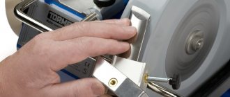
What is an adapter for a 4g modem
The quality of communication is influenced by many factors: distance to the base station, number of subscribers in this radius, 3G/4G network coverage. Due to the fact that it is not perfect everywhere, the connection can suffer greatly. This is especially true for residents of small towns and villages.
The only way to improve the quality of wireless Internet in areas with a weak signal is to install an outdoor radio antenna. Unstable cellular communication will improve by connecting special repeaters to the outdoor radio antenna, which increase mobile signal reception.
Note! Transceivers with an external radio antenna and WiFi distribution function allow you to get an online network on several devices at once.
Special antennas can be used in any premises, transport, or simply installed on the roof of a house. Due to technical features, it is impossible to directly connect to a router or 3G/4G modem to an external repeater, which increases the reception of a mobile signal. To do this, you need to use special adapters for the radio antenna, which consist of two RF connectors (high-frequency connectors) and a coaxial cable to connect the antenna amplifier to the transceiver.
The antenna adapter (Pigtail) on the side where the plug is located is connected to the device socket and must be sized for a 4G router. On the other hand, the connecting adapter is screwed onto the radio antenna wire.
Connectors with a threaded mechanism come in two types, paired with each other - with a male part and with a female part (with a hole).
Good quality pigtails for 4g modems will influence the success of signal amplification if the subscriber is located away from the base station.
The antenna design was proposed by Kharchenko K.P. in 1961 for receiving meter-wave television channels and for a long time was the most popular television antenna, receiving the name “zigzag”. See articles in the magazine "Radio" (Radio No. 3, No. 4, No. 8 1961; No. 11, 1962; No. 4, 1966; No. 10, 1967). Over time, the antenna was reconstructed for the UHF and other bands. With the advent of digital 3G and Wi-Fi networks operating at higher frequencies, the zigzag antenna migrated to them and established itself there as one of the best for DIY production.
In the West, such an antenna is called “BiQuad”, “Trevor Marshall's antenna”. It, like the triple square, is a type of loop antenna. Take a closer look: the Kharchenko antenna is two square frames combined into one system. The loop antenna, as is known, has such positive qualities as broadband and not critical to manufacturing accuracy. (Of course, this is no reason to make her a blunder
Television is transmitted in most cases with a horizontally polarized wave, and 3G, Wi-Fi, CDMA - with a vertically polarized wave. Therefore, for these networks, the “eight” should be in a “lying” position and resembles a kind of “glasses”.
On the Internet you can find many Kharchenko antenna designs for both Wi-Fi and 3G UMTS. Since the frequencies of these types of communications are close, it is important not to get confused here. You can use an online calculator and calculate the antenna directly for your range. In addition, you can find a list of links to HFSS optimized designs for most bands.
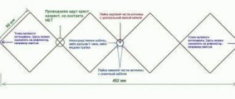
We also offer a calculator with Trevory Marshall's original Bi-Quad design. For specialists, I offer a file for MMANA. For 3G, the calculated side of the diamond is about 35 mm. But the network is full of designs with a side of 53 mm. Where is the truth? The truth is most likely 35 mm, and 53 mm is a typo (the numbers are in reverse order!), which was reproduced on the Internet using the copy-paste method. For an antenna with a side of 53 mm, the angles on the sides of the rhombus are not 90, but 120°, and the rhombus itself is made not of wire, but of a metal strip 8 mm wide. The antenna calculated by our online calculator has angles close to 90°. The gain of such an antenna is about 10 dBi.
The Kharchenko antenna calculation is also available in the Cantennator mobile Android application on Google Play, you can download it to your smartphone or tablet by clicking or scanning the QR code:
It is important to understand that the calculated dimensions of the reflector are the minimum acceptable. More is possible. For such a Wi-Fi antenna, a CD or DVD disc is quite suitable as a reflector. Its coating reflects radio waves in the centimeter range well; you just need to choose a disk that is not translucent when you look through it into the light. You can use a CD-DVD box for 25 discs as the basis for the antenna. I won't repeat myself.
This design is quite suitable for making an antenna for the CDMA-800 range (Intertelecom Ukraine). In this case, the size of the reflector approximately corresponds to an A4 sheet, and a wire or copper tube should be taken with a thickness of 5-8 mm (a copper strip of the same width can be used). To save money, the reflector can be made from tin. Dimensions - from the same calculator!
For the CDMA-450 range, the antenna dimensions are already up to half a meter wide, therefore, to reduce windage, it is better to use a reflector in the form of a grid.
You can use a construction mesh with a mesh size of no more than 1 cm, mounted on an H-shaped supporting structure made of any suitable metal. Since there is zero potential at the edges of the frame, it can be attached to the reflector with metal bolts. The frame is made of a 10mm wide duralumin strip, the joints are with aluminum rivets.
The antenna gain can be increased to 11-12 dBi by doubling the figure eight (Double BiQuad). Cross-feeding is used to phase the elements. How to do this is clear from the photo below. The antenna dimensions can be calculated using the online Double Bi-Quad antenna calculator on our website. In addition, diamonds can be replaced with circular loops. The result is a Bi-loop antenna that works on the same principle.
The finished antenna can be coated with nitro varnish, or painted with automotive paint to protect it from atmospheric influences if you intend to place it on a mast. On Wi-Fi and 3G bands, the Kharchenko antenna is quite critical to manufacturing accuracy. Therefore, having caught a signal, you should not neglect adjusting the antenna. You can use the standard “palmometer” of the modem, but specialized software is more convenient. By moving and spreading the “glasses”, as well as within small limits changing the distance to the reflector, the maximum level of the received signal is achieved. The main thing here is patience, since you need to constantly wait until the signal level readings in the program are updated.
Useful links:
- Kharchenko antenna for digital television
- Kharchenko's double zigzag for digital television
0
- VK()
- Facebook()
- Comments (48)
Comments
1234 5
#41 3G-Aerial admin 01/28/2018 20:52 You can, Ilgiz , use our online calculator, which will tell you the Wi-Fi frequency and dimensions, including wire diameter: Definitely DO NOT connect the central point.
Quote
#42 Ilgiz 01/28/2018 21:16 I quote 3G-Aerial admin:
You can, Ilgiz , use our online calculator, which will tell you both the Wi-Fi frequency and the dimensions, including the wire diameter: https://3g-aerial.biz/onlajn-raschety/raschety-antenn/raschet-antenny-kharchenko- zigzagoobraznoj Definitely DO NOT connect the central point.
Thanks a lot! and is a wire with a diameter of 1.7 mm suitable?) Quote
#43 Ilgiz 01/28/2018 22:37 This is the distance! (on the screen): //images.vfl.ru/ii/1517175365/9a5a9b61/20349376.jpg
- the post with the box (wi-fi point) is located a little lower in level compared to my house
Quote
#44 cezr4 04/03/2018 19:10 Indoors, the network picks up only near the window. Is it possible to connect two Kharchenko antennas to obtain a 3G signal repeater?
Quote
#45 3G-Aerial admin 04/07/2018 18:26 For Wi-Fi, this experience was a success. For 3G it may work, but maybe not. It all depends on the strength of the signal at the receiving point.
Quote
#46 php_proger 04/07/2018 20:25 I confirm, it will work, but you shouldn’t count on good coverage throughout the entire room. In my case, the distance to the operator’s base station is about 3 km in line of sight, there is a homemade panel antenna on the roof, about 12 m of RG-58 cable, which has high attenuation, in the room there is a Kharchenko antenna - a signal of -80-85 dB. At a distance of about 0.5 m from Kharchenko, the signal is lost.
Quote
#47 Igor Melnichenko 04/19/2018 18:39 Will anyone undertake to model an antenna for receiving any combination of digital television multiplexes in the 470-860 MHz band based on https://www.freepatent.ru/patents/2122762? But the exact location of the feeder connection along the width of the plates is not indicated
Quote
#48 Ruslan 12/13/2019 19:50 Hello, can you please tell me if it is possible to make two Kharchenko antennas for reception and transmission and connect them into one cable, just on the router one input operator Intertelecom is now working with one antenna at 859 MHz for one user, more or less, but two are bad enough do you recommend?
Quote
12345
Update list of comments
Add a comment
Comments from anonymous people (not registered site users) are pre-moderated. Moderation does not take place in real time and there may be a delay. We ask particularly impatient anonymous people not to publish the same post in a row. In this case, the post may be rejected by the moderator. Messages from disposable and non-existent emails are also deleted. The site has a forum and comments on social networks, where there are many more opportunities for communication.
©3G-Aerial
The principle of operation of a pigtail for a modem
Routers must have a special connector to connect it to the pigtail.
Review and configuration of the D-Link Dir-320 modem
Disadvantages of this connection method:
- you need to find an adapter with a response connector suitable specifically for this modem;
- The socket is very fragile and careless connections can damage or break it.
It is rarely connected directly to the antenna cable, since the 4G modem is a small device and the best way to connect it is through the appropriate adapter.
The antenna wire is hard and has a diameter of 7 to 10 mm, which will not allow inserting a plug for a 4g modem, so you have to use a short adapter made of soft wire - a pigtail.
Note! The function of the cable adapter is to provide a flexible connection between the USB modem and the radio antenna, the wire of which is usually thick and rigid.
How to choose the right pigtail for a modem
The industry produces a huge selection of different adapters with different types of connectors.
What are the differences between 3G and 4G networks: features, advantages and disadvantages
Antenna adapters differ in the connectors connected to modems. You need to choose an adapter that matches the size of the network port on the modem and on the cable assembly. They may differ in material, size and other indicators.
Note! The most popular adapters are CRC9 and TS9, depending on the model used.
Adapters TS9 and CRC9 are visually very similar, differing only in diameters. The TS9 has a slightly larger diameter socket and adapter plug.
To select an antenna adapter for a 3G/4G device, you need to make sure that the connector is suitable for it. If the diameter of the plug is not selected correctly, it will not be supported in the network port of the device.
Homemade log-periodic antenna for a GSM modem. Manufacturing and connection
We live on the edge of a small village.
Faced with the need for the Internet at home, we began to study what modern infrastructure offers in this sense. It turned out that the most affordable and easiest way to connect to the World Wide Web is a GSM modem, inexpensive versions of which are often called a USB whistle. Such a modem is inexpensive, widespread and works well, but only in the area of reliable signal reception of a cellular network base station. In the city, please be kind, but outside of it, it greatly depends on how developed the mobile network is. Often a modem requires a good external antenna raised to a certain height. Models of devices with connectors for connecting an external antenna are considered a kind of professional communication device and cost ten times more.
To work, you will need a minimum set of radio installation and plumbing tools, and a little patience. For working with small items, a special visor with magnifying glasses or a lamp with them is very useful. Make sure you have good lighting.
However, even in a simple “USB whistle” there is a technological connector for an antenna inside the case and you can use it. Some modems have access to the antenna connector, some do not; in the latter case, you will have to modify the plastic case, which will void the device's warranty. The antenna connector of a budget modem is very flimsy in design and is installed directly on the printed circuit board using the surface mount method. That is, it only holds on to the rations.
Only a sufficiently thin (flexible) coaxial cable should be connected to it, otherwise there is a high probability that the thick and rigid cable will break the connector. Thin cables have increased HF losses and should not be used for the entire feeder. In principle, there are adapters - a modem connector - 15...20 cm of thin cable - a larger connector for connecting a good external antenna cable. Such an adapter allows us to solve the problem of mechanical load on a weak connector, but we find ourselves tied to a specific connector at the output of the adapter, which is unreasonable in the case of a homemade antenna; moreover, such adapters are extremely rare on sale. It is also worth remembering that each additional connector, even each solder on the cable, introduces RF attenuation.
My connection option - I picked up a fairly flexible television cable in the store - without a foil screen, the central core is copper (soldered well) and multi-core (flexible). The connection looked like this.
A piece of thick tinned copper wire (resistor leg) is soldered to the central core. Its thickness is such that it fits tightly into the nest. The cutting area is insulated with a thermal tube.
The pin is inserted all the way into the connector and the twisted and tinned cable braid is soldered to the “ground” of the antenna socket.
The soldering area is insulated, and most importantly, the thin area on the cable is reinforced with several layers of thermal tube. Now all that remains is to try it on and, if necessary, file the plastic case so that it closes properly, with our modification. You will have to handle it carefully.
That's it, the modem is connected.
Let's move on to the calculation and manufacture of the antenna.
Antenna type, “log-periodic” was selected, the accepted foreign abbreviation is LPA antenna. Its features are high gain and a very narrow (sharp) radiation pattern. In addition, with sufficiently careful manufacturing, the antenna will not require adjustment, which cannot be done without specialized RF measuring instruments.
You can calculate our antenna in one of the network services by finding it using keywords, or in a special program, for example Logo_Periodic_Calculate it can be found here.
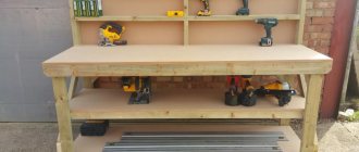
We prepare the necessary materials and tools. At the first stage, we need to cut two strips of one-sided foil fiberglass 10mm wide, 1.5-2mm thick, and long - according to calculations. We will also need trimmings of “bare” copper wire with a diameter of 1.5-2.5 mm, which can be removed, say, from a cable for internal electrical wiring. Well, accordingly, a soldering iron, rosin, a ruler and wire cutters.
We cut elements of the same size, 5-10mm larger than the longest vibrator, referring to the calculations made. We mark the location of the antenna elements on the improvised “boom”. Next, we carefully solder them, without overheating the substrate, and use wire cutters to bring them to the required size. It should be remembered that we are dealing with RF with its skin effect (propagation of currents in a thin surface layer), in this sense, “cold solders” and heavily scratched surfaces should not be allowed. It is good practice to use a special flux with glycerin to obtain a mirror-like surface for soldering.
Now, you need to rigidly fasten the finished “booms” opposite each other at the calculated distance and close the rear parts with a jumper. A coaxial cable is connected to the front ends - the central core is at one end, and the shielding braid is at the other.
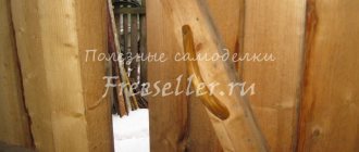
My version of the antenna is on a polypropylene pipe. A suitable piece of pipe was sawn on a circular saw to obtain flat areas convenient for attaching the boom halves. They were attached with adhesive tape. At the back of the antenna there is a place for the modem - initially it was decided to shorten the antenna cable as much as possible, place the modem near the antenna and perform the reduction “digitally”. The plastic pipe was taken a little longer to obtain a convenient dielectric “handle”.
Another angle of the antenna, the seats of the boom halves and the cable connection are visible. I recommend that you get acquainted with a slightly different, perhaps more successful antenna design.
The finished antenna was taken outside to test its functionality and secured at the end of a long ladder with wire.
Due to the inconvenience of orientation, it was necessary to make a rotating unit. Some metalwork, cutting stainless steel, welding work.
The rotating unit turned out to be somewhat cumbersome, but unlike a similar satellite dish unit, it allows you to orient the antenna much more accurately.
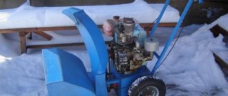
The turning unit is welded to the mounting plate at an angle of just over 90 degrees (so that water can drain). During work, we ran out of stainless electrodes, so we had to use regular ones - hence the painted welding seams. In the photo above, the unit worked on the roof in different places, with different antennas, for about two years and generally proved to be reliable and convenient. In the photo, an antenna with a USB modem is installed on the roof gable. The rotation angles allow you to orient the antenna towards a cell tower in a neighboring village (~5 km).
In a sealed box next to the antenna, the modem and the modem power supply. In general, the entire connection diagram looks like this.
The problem with long USB connections is the drop in supply voltage on long and relatively thin power wires (the principle of operation of the device via a USB port - including powering the device from the port itself). You can lengthen the USB cable within reasonable limits in two ways - increase the cross-section (reduce resistance) of the power conductors or power the device from your nearby power supply. The goal of both methods is to ensure that the supply voltage on our device is as close to five volts as possible. Plus.
Increasing the cross-section of the supply wires has already been tested during test activations of the antenna “on the stairs”. There was a connection and access to the network, but it did not work stably - it was interrupted periodically.
To place the antenna with the rotation unit, another place was chosen - the pediment of the roof of the house. The distance to it is somewhat greater and it was decided to place the power supply “at the top” - near the modem, eliminating the possible cause of failures. The “long” USB connection was made of two thin coaxial cables (central cores - two data lines, shields to a common wire).
What happened was the placement on the roof gable (access from the flat roof of the woodshed via a short ladder) and the general configuration of the equipment, which subsequently made it possible to conveniently experiment with different types of antennas. At that time, it was possible to connect relatively stably to the GSM (2G), sometimes WCDMA (3G) network. The antenna itself performed well. Some painstaking manufacturing (many precise dimensions) pays off in the absence of tuning and high gain. The antenna also has a low windage and is not very attractive to birds.
Looking ahead. The reason for the unstable operation of the modem turned out to be the long USB cable, despite the well-being of the device’s power supply. Perhaps it was a matter of the type or even the type of modem, because there are descriptions of similar “extension cords” and larger footage on the Internet.
The manufacture and testing of two more types of antennas will be described separately.
Become the author of the site, publish your own articles, descriptions of homemade products and pay for the text. Read more here.
How to determine what pigtail is needed?
On the antenna wire side, these are usually F or SMA sockets; the modem uses CRC9 or TS9 type sockets for connection.
How to share Internet from iPhone via USB to external devices
Antenna connectors are not universal, due to the fact that each manufacturer of mobile devices puts connectors on their products that are structurally different from competitors, as a result, it turns out that each device requires its own special adapter.
Their main differences are:
- in different diameters and plug lengths;
- incompatible with different models;
- different types of connectors for connecting to the radio antenna cord.
Note! Huawei uses mainly the CRC9 connector in its mobile devices, while Novatel Wireless uses mainly the TS9 connector.
The connectors on the antenna wire side also come in different types. This can be F and FME models. For type F connection, an F adapter is screwed onto the cable side.
The CRC9-F antenna adapter is suitable for all modems and routers in which the pigtail connector for a 4g modem is connected to the device port with a CRC-9 tip. F is the designation of the connector on the other end of the adapter for connecting to the antenna wire.
The TS9 FME adapter has a TS9 connector on the side connecting to the modem, and an FME connector on the side connecting to the radio antenna.