Car owners of both domestic cars and foreign cars may from time to time encounter the problem of electrical inoperability. Some car enthusiasts, when solving such problems, turn to specialized electricians, others try to get rid of the problem on their own. One of the main devices used for testing wiring is a probe. How to make an auto electrician's test sample with your own hands and what tools should be in a specialist's arsenal - read below.
[Hide]
Basic set of tools and equipment for an auto electrician
A homemade probe made from a medical syringe, a nail and a light bulb.
An auto electrician’s tool includes the following components and devices:
- Auto electrician tester with lamp. At first glance, it may seem that such devices have already become obsolete, but in practice, many issues can be resolved with their help. The purpose of the device is to diagnose the presence of current in an electrical circuit, so such a probe can be used for many tasks.
- A more powerful probe, as can be seen from the photo, it uses a powerful light bulb compared to the devices described above. Its purpose is similar, only thanks to the use of a more powerful light bulb, this auto electrician’s tool allows you to check not only the presence of voltage in a section of the circuit, but also identify bad contacts, as well as possible short circuits.
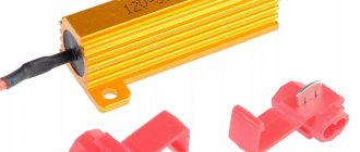
- Every electrician should have a long cable in his arsenal that is used to supply power to the damaged area. The crocodile wire is connected to the positive terminal of the battery; such a device is used to find a short circuit in the electrical network. To ensure reliable operation of the tester, the wire must be protected by a safety element.
- A professional tool for an auto electrician is a multimeter. If you decide to do wiring repairs, you can buy an entry-level tester; it allows you to measure resistance, DC voltage and current parameters. In this case, the direct current measurement value must be at least 20 amperes; this will not be the case in cheaper devices. If you buy a Chinese-made device, then over time you will most likely be faced with the need to install new probes. Because standard ones, as practice shows, do not work for long.
- Also, an auto electrician’s tool should include other tools, in particular, a soldering iron with consumables, pliers, screwdrivers, wrenches, electrical tape, etc.
Ohmmeter probe
Sound probe-ohmmeter with mega mode and low resistance mode.
This simple and convenient homemade device is used to check the integrity of a de-energized electrical circuit, locate the location of the fault, and approximate the resistance of circuit elements. The device consists of a series-connected electromagnetic pointer head, a galvanic element, a resistor - a current limiter through the head and cords with probes. It is advisable to select an electromagnetic head with a current of full deflection of the needle within the range of 100 µA - 1 mA. Heads from any voltmeter, milliammeter or ammeter are suitable for this purpose. Instrument heads that measure the recording level in tape recorders are also convenient.
You need to remove the additional resistor from the head of the voltmeter, replacing it with a piece of conductor, and cut off the shunt in the head of the milliammeter and ammeter. One 1.5 V element is used as a battery.
The resistance of current limiting resistors is calculated as the ratio of the voltage of the battery to the current of the total deflection of the instrument needle. For example, for a 1.5 V element the resistor should have a resistance of 1.5 kOhm. After assembling the ohmmeter, the resistor can be selected more accurately by connecting in parallel to a calculated resistor with a resistance several tens of times greater (if the arrow does not reach the end of the scale), or by connecting in series a second resistance several tens of times less (if the arrow is off scale).
For the ohmmeter body, you can use a plastic box of suitable size. It is convenient to make probes from collet pencils or ballpoint pen bodies.
Instructions for making a tester
If you need a device to measure the presence of voltage in the on-board network, then you don’t have to spend money on an expensive tester. To begin with, you can try to build your own simple car tester using LEDs or usually an incandescent light bulb. We will tell you how to make a simple tester from a light bulb and a syringe, as in the photo at the beginning of the article (the author of the video is Vyacheslav Chistov).
Stages
The manufacturing procedure for the device is as follows:
- To begin, you will need a regular medical syringe, which can be purchased at any pharmacy. Of course, we take not a small one, but a larger syringe - 10 or 20 cubic meters.
- Take a small nail and install it into the body of the previously prepared syringe. To do this, the upper, moving part of the syringe (not the flask) must be removed and a nail installed instead of a needle. In this case, its cap must be securely fixed in the hole. Before installation, make sure that the nail is as sharp as possible and should not be blunt.
- To the end of the nail you need to solder either an LED element or a regular incandescent light bulb, the power of which is 1 W. To do this, use a soldering iron with tin and rosin. The light bulb should be fixed as securely as possible so that it does not fall off over time.
- To the other end of a diode or a regular light bulb, you need to solder a wire with a pre-installed crocodile clip on it. There must also be a reliable and durable connection here to prevent accelerated wear of the structure.
- The resulting probe design can be encased in epoxy resin to ensure safety and reliability. After completing all these steps, you will receive a full-fledged probe that will allow you to determine the presence of voltage in the car’s electrical network. If for some reason the device does not work, check the quality of soldering of all components and the functionality of the light bulb or LED itself.
Price issue
1. Professional control UR-MAX AVM-1 PRO (price - about 2500 rubles)
2. A simpler model of the tester UR-MAX AVM-1 Light (price - about 1300 rubles)
3. Multimeter model DT-830B (price - 400 rubles)
Homemade LED dialer. Simple probes, attachments, meters
01.06.2019
And industrial devices with LEDs. They are found almost everywhere today. They are also starting to use LEDs instead of old tubular fluorescent lamps, but we can keep silent about incandescent lamps. Due to the fact that there is a huge variety of diodes, to check them it will be useful to have a tester, or make one yourself.
Of course, some LEDs can be checked with a regular multimeter in dial mode. The LED should light up. But if it operates at a higher voltage than the multimeter outputs, the glow will be very weak or not at all. For some white, yellow and blue LEDs, the voltage can reach 3.3V.
First of all, when testing an LED, you need to determine where its cathode is and where its anode is. Of course, this can be determined by examining the insides of the crystal, but this takes time, effort, nerves, and in general this is an unprofessional approach.
Among other things, the manufactured probe will help determine what operating voltage the LED has, and this is a very important parameter. And finally, the device will help you trivially determine the serviceability of the LED.
Device diagram
According to the author, the device circuit is very simple. The homemade product is an attachment that plugs into the socket of a multimeter.
Materials and tools for homemade work: - connecting block from a Krona type battery; - working battery (needed to power the probe); — a miniature button without locking (a clock button from a phone, tablet, etc. is also suitable); — one 1 kOhm resistor for 0.25 W; — quick-release connector for transistors (socket with a pitch of 2.54 mm, a total of 3 contacts will be needed); — material for creating a housing for the device (a plastic plate, etc. will do); - four brass screws.
Homemade manufacturing process:
Step one. We prepare the necessary elements
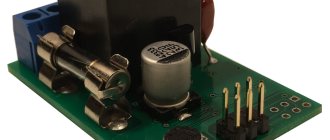
First you need to prepare the contacts that will connect to the multimeter. The photo shows that the pins have threads, but it is best to get rid of them. The thread is needed only to screw the elements using nuts to the plastic body.
To attach the pins, you need to drill fourth holes in the plastic plate. Two are needed to install the connecting block through which the Krona battery is connected. And the second two are needed for mounting the contacts with which the device is connected to the multimeter.
To attach the microbutton and the connector for transistors, you will need to cut the board out of PCB.
Step two.
Soldering the circuit Now you need to solder the electronic parts, guided by the circuit presented above.
You need to solder a microbutton, a transistor socket and a 1 kOhm 0.25 W resistor. Step three.
The final stage. Assembling the homemade product Now the device is assembled into a common housing. The removed wires are connected to the power block for the Krona battery and the plugs with which the probe is connected to the multimeter. On the PCB board near the connector, the author glued a circuit that allows you to avoid confusion when testing the LED. The red power wire is the “plus”, that is, the anode. Well, the black one with a minus sign is the cathode. To test the LED, you need to plug it into the connector and connect the Krona battery to the socket. Now the multimeter switches to voltage measurement mode in the range of 2-20V DC. If the diode is working and turned on correctly, it will light up.
As mentioned at the beginning, you can use a multimeter to determine the operating voltage of the LED, but if this is not necessary, a multimeter is not needed at all. That's all, the little helper is ready, now it will be much more pleasant and faster to assemble homemade products with LEDs or repair something.
Probe 1 Developed by the author V. GRICHKO from Krasnodar, you can check the presence of voltage in the controlled circuit, determine its type (constant or alternating), and also carry out a “test” of the circuits for serviceability. The device diagram is shown in Fig. 1
The HL2 LED indicates the presence of a constant voltage of a certain polarity at the input (plugs XP1 and XP2). If positive voltage is supplied to plug XP1, and negative voltage is supplied to XP2, current flows through current-limiting resistor R2, protective diode VD2, zener diode VD3 and LED HL2, so LED HL2 will light. Moreover, the brightness of its glow depends on the input voltage. If the polarity of the input voltage is reversed, it will not glow. The HL1 LED indicates the presence of alternating voltage at the input of the device. It is connected through current-limiting capacitor C1 and resistor R3, diode VD1 protects this LED from the negative half-wave of alternating voltage. Simultaneously with LED HL1, HL2 will also light. Resistor R1 serves to discharge capacitor C1. The minimum indicated voltage is 8 V. A high-capacity ionistor C2 is used as a source of constant voltage for the “continuity” mode of connecting wires. It must be charged before testing. To do this, connect the device to a 220 V network for about fifteen minutes. The ionistor is charged through elements R2, VD2, HL2, the voltage on it is limited by the zener diode VD3. After this, the device input is connected to the circuit being tested and the SB1 button is pressed. If the wire is corrected, current will flow through it, the contacts of this button, LED HL3, resistors R4, R5 and fuse link FU1 and LED HL3 will light up, signaling this. The energy reserve in the ionistor is sufficient for the continuous glow of this LED for about 20 minutes. The limiting diode VD4 (limiting voltage does not exceed 10.5 V) together with the fuse link FU1 protects the capacitor from high voltage if the SB1 button is accidentally pressed while monitoring the input voltage or charging the capacitor. The fuse link will burn out and will need to be replaced. The device uses resistors MLT, C2-23, capacitor C1 - K73-17v, diodes I N4007 can be replaced with diodes 1N4004, 1N4005, 1 N4006, zener diode 1N4733 - with 1N5338B. All parts are mounted on a prototype circuit board using wire wiring.
Samples 2
In the form of a probe, it is assembled on LEDs and, in addition to “testing” the circuits, allows you to determine the type of voltage (DC or AC) and approximately estimate its value in the range from 12 to 380 V. The author of this device is A. GONCHAR from the city of Rudny, Kustanai region. Kazakhstan. Due to the nature of his activity, he often has to monitor the performance and repair various devices that use different (36, 100, 220 and 380 V) direct and alternating voltages. For testing such circuits, the proposed probe is very convenient, since it does not require switching at different controlled voltages. When developing this device, the probe was taken as a basis, the description of which was published in Radio No. 4, 2003, on p. 57 (Sorokoumov V. “Universal probe-indicator”). It has been modified to expand its functionality. The diagram of the upgraded probe is shown in Fig. 2
It contains a quenching resistor R1, a scale of two-color LEDs HL1-HL5, a storage capacitor C1 and a phase wire indicator on a neon lamp HL7. The device can operate in three modes: voltage indicator, phase wire indicator and “continuity” - an indicator of the conductivity of the electrical circuit. To indicate voltage, the input of the device - pin XP1 inserted into socket XS2, and socket XS1 (using a flexible insulated wire) is connected to the controlled points. Depending on the potential difference between these points, different current flows through resistors R1-R6 and the zener diode VD1. As the input voltage increases, the current also increases, which leads to an increase in the voltage across resistors R2-R6. LEDs HL1-HL5 light up one by one, signaling the value of the input voltage. The values of resistors R2-R6 are selected so that at a voltage of 12 V or more the HL5 LED lights up, 36 V or more - HL4. 127 V and more - HL3, 220 V and more - HL2 and 380 V and more - H1_1. Depending on the polarity of the input voltage, the color of the glow will be different. If pin XP1 is plus relative to socket XS1. The LEDs light up red, if negative - green. With variable input voltage, the glow color is yellow. It should be noted that with an alternating or negative input voltage, the HL6 LED may also light up. In the phase wire indicator mode in the network, any of the inputs (XP1 or XS2) is connected to the controlled circuit and the E1 sensor is touched with a finger. The neon indicator lamp will light up if this circuit is connected to a phase wire. To use the device for “testing” circuits, you must first charge the storage capacitor C1. To do this, the input of the device is connected for 15...20 s to a 220 V network or to a constant voltage source of 12 V or more (plus to the XP1 plug). During this time, capacitor C1 will have time to charge through the diode VD2 to a voltage slightly less than 5 V (it is limited by the zener diode VD1). When subsequently connected to the controlled circuit, if it is working properly, the capacitor will be discharged through it. resistor R7 and LED HL6, which will light up. If the test is carried out briefly, then charging the capacitor will be enough for several tests, after which the charging of the capacitor should be repeated.
Fixed resistors R1 - PEV-10 were used. the rest are MLT, S2-23. capacitor - K50-35 or imported, diode KD102B can be replaced with any diode from the 1N400x series, zener diode KS147A - with KS156A, instead of two-color LEDs, you can use two different colors of light, turning them on back-to-back, it is advisable to use the HL6 LED with increased brightness . It should be noted that LEDs of different glow colors have different forward voltage values, so their switching thresholds at different input voltage polarities will not be the same. Most of the parts are placed on a PCB or getinax board; holes are made for their pins and wired wiring is used. LEDs HL1-HL5 are installed in a row. Since the housing from a faulty gas piezo lighter was used as the probe body, the board is designed for installation into it (Fig. 3).
The hole in the body intended for the piezo lighter button is covered with plexiglass. All LEDs and neon lamp are placed on the board so that they can be seen through this hole. Socket XS1 is placed on the side wall of the case, XS2 - at the end. A screw, also located on the side wall, can be used as a sensor. A plug with a flexible wire and an alligator clip at the other end is inserted into socket XS1, and a metal pin, pointed at the end, is inserted into socket XS2 for more convenient connection to small-sized contacts (Fig. 4).
When assembling, testing and operating the described device, you should remember the safety rules when working with high voltage.
A primitive “test” - an electric cartridge with two wires and a lamp - is far from the best device for “testing” electrical circuits. Industrially produced testers and avometers are also, as they say, not a gift, especially when you have to deal with modern technology, and they are not cheap. So electricians have to create indicator probes themselves - universal, compact and reliable. The magazine “Modelist-Constructor” spoke about one of these devices in No. 5 for 1990.
Having made myself this sampler, developed, by the way, by a talented representative of the rural outback, at first I couldn’t get enough of it. The device is truly a reliable assistant for the installer, allowing you not only to check electrical circuits, but also individual elements - diodes, transistors, capacitors, resistors. Assembled in the body of a toy gun and equipped with probes, it also makes it possible to control alternating and direct voltage from 1 to 400 V, detect the phase and neutral wires of the network, and evaluate the insulation resistance of electrical equipment.
However, over time, a discrepancy has emerged between the real capabilities of the indicator probe and the requirements that the ever-increasing complexity of electrical and radio engineering places on such devices. In particular, the complexity of detecting voltage in DC circuits and finding out whether the extinguished signal LED indicates a de-energized wire line or a short circuit is no longer satisfactory. Therefore, the device had to be modernized. Minimal changes have been made (parts HL2, NL3, R5 and cut “a” on the circuit board), but the universal probe-indicator is now back in use.
As before, the device is based on a DC amplifier using transistors \/T1 -\/T2, the load of which is the LED HL1. Resistors R1 and RЗ limit I6 of semiconductor triodes. Capacitor C1 creates a negative feedback circuit for alternating current, eliminating false indications from external noise. Resistor R4 in the VT2 base circuit is used to set the required resistance measurement limit. Resistor R2 limits I measurement when the probe operates in AC and DC circuits. Diode VD1 performs the function of a half-wave rectifier. LEDs HL2 and HL3 are polarity indicators, the current through which is limited by resistor R5.
In the initial state, the transistors are closed and the HL1 indicator does not light. But if the probes are connected to each other or connected to a de-energized, serviceable circuit with an Rc of no more than 500 kOhm, then NL1 lights up. The brightness of its glow is inversely proportional to the resistance of the circuit being tested.
When the probe is connected to the AC circuit, the positive half-waves open the transistors, and the HL1 LED lights up. Additional indicators HL2 and HL3 at the device input also light up. If the voltage is constant, then NL1 and NL3 will light up when there is a “plus” on the X2 probe (if the voltage polarity in the circuit being tested is different, they will go out, but the HL2 LED will light up).
As when working with the device before modernization, the serviceability of diodes and transistors is checked by comparing p-n junctions. The absence of a glow indicates a break, but if the NI is constantly on, then there is a breakdown in the junction under test.
When a working capacitor is connected to the probe, the HL1 LED flashes and then goes off. The brightness and duration of the flash depend on the electrical capacity being tested. When the capacitor is broken or has a large leak, the indicator light is constantly on.
“Phase” is determined as follows: probe X1 is taken in the hand, and probe X2 is touched to the wire under test. If the HL1 LED is on, then the “phase”, as they say, is evident.
The methods of other checks have not changed, but working with the modernized indicator probe is still more convenient and faster than before, because three LED indicators act as informants.
V.TOKAR, Sumy, Ukraine
Noticed a mistake? Select it and press Ctrl+Enter
to let us know.
These devices are designed to check (check) the installation of assembled structures, check the correctness of connections and compliance with the circuit diagram.
An undoubted convenience of probes is the presence of an alarm system, which allows you to monitor the integrity of a particular circuit. One of the possible probe circuits is shown in
Fig. 1 . It contains three low-power transistors, two resistors, an LED and a power supply.
In the initial state, all transistors are off, since there is no bias voltage at their bases relative to the emitter. If you connect the terminals “To the clamp” and “To the electrode” together, a current will flow in the base circuit of transistor VT1, the value of which depends on the resistance of resistor R1. The transistor will open, and a voltage drop will appear across its collector load, resistor R2. As a result, transistors VT2 and VT3 will open and current will flow through the LED VD1. The LED will flash, which will serve as a signal that the circuit being tested is working properly.
The probe can be assembled in any version.
Like one of them in the form of a small plastic case that can be attached to a watch strap. At the bottom of the strap (opposite the body, a metal plate is attached - an electrode connected to a resistor R1. When the strap is fastened on the hand, the electrode is pressed against it. In this case, the fingers act as a probe probe. When using a bracelet, no additional plate - an electrode is needed - the resistor output R1 is connected to the bracelet. The probe clamp is connected, for example, to one of the ends of the conductor, which needs to be found in the harness or “ringed” in the installation. By touching the ends of the conductors on the other side of the harness with your fingers one by one, the desired conductor is found by the appearance of the LED glow. In this case Between the probe and the clamp, not only the resistance of the conductor, but the resistance of part of the hand turns on. Nevertheless, the current passing through this circuit is enough for the probe to “work" and the LED to flash. Transistor VT1 can be any of the KT315 series with a static current transfer coefficient of at least 50 , VT2 and VT3 - any low-power low-frequency, appropriate structure and with a current transfer coefficient of at least 60 (VT2) and 20 (VT3). The AL102 LED is economical (consumes no more than 5 mA current) and has a low brightness. If it is not sufficient for your purposes, you can install an AL102B LED. In this case, the current consumption will increase several times (of course at the time of indication). Power source - two D-0.06 or D 0.07 batteries connected in series. There is no power switch in the probe, since in the initial state (with the base circuit of the first transistor open) the transistors are closed, and the current consumption is negligible - it is comparable to the self-discharge current of the power source. The probe can also be assembled using transistors of the same structure, for example, according to the diagram shown in
Fig. 2 .
True, it contains slightly more parts than the previous design, but its input part is protected from electromagnetic circuits, which sometimes lead to false flashing of the LED. This probe uses silicon transistors of the KT315 series, characterized by a low collector junction current over a wide temperature range. When using transistors with a current transfer coefficient of 25 ... 30, the input resistance of the probe will be 10 ... 25 MΩ. Increasing the input resistance is impractical due to the likelihood of false indication by external interference and extraneous conductivity. As in the previous case, in its initial state the device consumes virtually no energy. Current consumption in indication mode does not exceed 6 mA. You can adjust the input resistance of the device by selecting resistor R3, having previously connected a chain of resistors with a total resistance of 10 ... 25 MΩ to the input and achieving the minimum brightness of the LED. If there is no LED, instead of it you can use a small-sized incandescent lamp with a voltage of 2.5 V and a current consumption of 0.068 A (for example, an MH 2.5-0.068 lamp).
True, in this case you will have to reduce the resistance of resistor R1 to about 10 kOhm and select it more accurately according to the brightness of the lamp with closed input conductors. Sound indication can also be used in probe circuits. A diagram of one of them, attached to the hand using a bracelet, is shown in Fig. 3
.
It consists of a sensitive electronic switch on transistors VT1, VT4 and an audio frequency generator (AF) assembled on transistors VT2, VT3 and a miniature telephone BF1. The oscillation frequency of the generator is equal to the mechanical resonance frequency of the telephone. Capacitor C1 reduces the influence of alternating current interference on the operation of the indicator. Resistor R2 limits the collector current of transistor VT1, and therefore the current of the transistor junction VT4. Resistor R4 sets the highest volume of the telephone sound, resistor R5 affects the reliability of the generator when the supply voltage changes. The BF1 sound emitter can be any miniature telephone with a resistance from 16 to 150 ohms. Power source - battery D-0.06 or similar. Transistors - any silicon of the appropriate structure, with a current transfer coefficient of at least 100 and a reverse collector current of no more than 1 µA. The structure is mounted on an insulating strip or board made of one-sided foil fiberglass. The bar (or board) is placed, for example, in a metal case in the form of a wristwatch, to which a metal bracelet is connected. Opposite the emitter, a hole is cut out in the housing cover, a miniature socket of the XT1 connector is fixed on the side wall, into which an extension conductor with an XP1 probe (it can be an alligator clip) is inserted at the end. A slightly different probe circuit is shown in
Fig. 4 .
It uses both silicon and germanium transistors. Capacitor C2 shunts the electronic switch via alternating current, and capacitor C3 is the power source. It is advisable to select transistor VT1 with a current transfer coefficient of at least 120 and a reverse collector current of less than 5 µA, VT2 - with a transfer coefficient of at least 50, VT3 and VT4 - at least 20 (and a reverse collector current of no more than 10 µA). Sound emitter BF1 - capsule DEM-4 (or similar) with a resistance of 60 ... 130 Ohms. Probes with sound indication consume slightly more current than the previous ones, so during long breaks in operation it is advisable to turn off the power source.
In Fig.5
shows a diagram of a probe - ohmmeter.
It may be necessary if during “diagnosis” it is also desirable to measure the approximate resistance of the circuit. The range of resistances it measures is from units of ohms to 25 MOhms. The ohmmeter circuit is made up of the probe shown in
Fig. 2 .
Only in an ohmmeter, in parallel with resistor R3, one of the resistors R5 - R7 is connected (depending on the measurement range). While probes XP1 and XP2 are open (nothing is connected), the transistors are closed and the probe does not consume current from source GB1. But as soon as you connect the probes, for example, to some kind of resistor, current will flow in the base circuit of the composite transistor VT1VT2. The resistance of the collector-emitter section of transistor VT2 will decrease and a current will also flow in its circuit, which will create a voltage drop at the emitter junction of transistor VT3. It will be greater, the lower the resistance of the resistor being tested and the greater the resistance of the lower arm of the divider resistor (resistor R3 and one of the resistors R5 - R7). In the position of push-button switches SB1 - SB3 shown in the diagram, this voltage will be sufficient to open transistor VT3 and light the LED when the resistance of the resistor (or circuit) being tested is less than 25 MOhm. If you press the SB1 switch button, the LED will light up only with a resistance of up to 1 MOhm. When you press the remaining buttons, the LED will only respond to resistance that does not exceed the limit indicated by the button. Transistors can be of the KT306, KT312, KT315 series with any letter index, but possibly a higher transmission coefficient and lower reverse collector current. LED - AL102A, AL102G, AL307A. Resistors MLT-0.125 or MLT-0.25. The remaining parts are of any type. Setting up the probe comes down to setting the selected measurement limits. First, select the probe probes to a chain of series-connected resistors with a total resistance of 25 MOhm and select the resistor R3 to achieve the minimum brightness of the LED. Then the probes are connected to a resistor with a resistance of 1 MOhm and the same results are achieved by selecting resistor R5 with the SB1 switch button pressed. Proceed similarly for the remaining measurement limits. It should be noted that the LED flashes brighter, the greater the current transfer coefficient of transistor VT3. The maximum current consumed by the probe in measurement mode does not exceed 10 mA.
When working with a 220 Volt electrical network, you have to make some measurements. First of all, this is a check for the presence of voltage, and in this case we are interested in the result - there is voltage or not. When checking wires, switches, etc. you need a dialing device. In this case, the result is also satisfactory - there is a chain, there is no chain. When checking the integrity of light bulbs and other electrical appliances, it is also enough to ring the circuit, making sure there are no breaks. Therefore, the tester is inconvenient and not needed at all for working with electrical wiring. Need a universal probe
to check the presence of voltage and to test circuits with load assessment - a circuit with zero resistance (wire) or a circuit with a load.
The diagram of such an electrician's probe
is shown in Fig. 1. In the initial state, when nothing is pressed, the probe operates in the mode of a two-pole voltage indicator. The voltage is estimated by the glow of two red LEDs HL1, HL2 and a neon light bulb La1. Up to a voltage of 100 volts, only the LEDs light up, and by the brightness of the glow you can roughly estimate the voltage value. The LEDs begin to glow at a voltage of about 2 Volts. With alternating current, both LEDs light up, with constant current, only one of the two. You can determine the polarity of the voltage by marking both LEDs with plus and minus signs. When the voltage is more than 100 volts, a neon light comes on in addition to the LEDs. It’s very clear right away - all the indicators are shining - so be careful. To search for a phase, an additional circuit of a single-pole voltage indicator is built into the probe. To determine the phase wire, you need to touch the contact of the indicator (without touching the clamp - it must be in the transport position) and touch the wires being tested with a probe. The glow of the neon indicator indicates the presence of voltage on the phase wire. To test the circuit, press and hold the S1 button.
In the first mode, continuity testing is carried out through an LED with a limiting resistor. Power is supplied by two finger or little finger batteries. The HL3 LED will light up when the resistance of the dialed circuit increases to almost 10 kOhm. The disadvantage of the LED indicator is that it does not distinguish a completely short-circuited circuit from a large load (300 W and above) - the glow of the indicator due to the equalizing effect of the ballast resistor R3 is almost the same. For evaluating shorted circuits, fuses, wires, etc. switch the probe (S2) to low resistance mode. Now a regular light bulb from a 2.5 V flashlight operates through the battery circuit. The resistance of the light bulb is low, the current through it is 0.15 Ampere, so the presence of any slight circuit resistance of more than 5 Ohms will cause the light bulb to go out. Therefore, this mode is excellent for identifying wires. The device fits very well in a long plastic case, like a toothbrush case. It is convenient to make the probe of the device folding, then you can carry it in your pocket. The device can be significantly simplified by leaving only an LED indicator without neon and only LED dialing. The information content, of course, immediately decreases.
The simplified probe circuit is shown in Fig. 4. It is good to have such a probe as part of a small tool kit - it takes up little space.
When an electrician and a control engineer works in industrial electrical installations, the set of functions even for a universal probe according to the scheme in Fig. 1 is a little not enough. You always have to take a tester with you to measure, for example, phase imbalance or the resistance of the motor windings in order to identify its damage. By the way, the presence of short-circuited turns, if there are only a few of them, cannot be determined even with a digital multimeter, and the engine will heat up. There is a method for determining short-circuited turns in electric motors, transformers, chokes and other coils with high inductance. Evaluate the occurrence of self-inductive emf when turning off the current through the inductance. In the presence of high inductance and quality factor, the self-inductive emf that occurs at the ends of the coil when the current is turned off is several tens or even hundreds of times higher than the supplied voltage. If at this moment a neon light bulb is connected to the ends of the coil, it will flash brightly. Naturally, the light bulb must be protected by a limiting resistor. A separate diagram of such a probe is shown in Fig. 2.
When the power is turned on with toggle switch S1, the connected inductance is powered from the power source. The current in this circuit is limited only by the inductance resistance and the internal resistance of the source. A light bulb (or LED) serves as an indicator that the current is turned on. The neon indicator is connected in parallel to the coil through a limiting resistor. When you press button S2, the current through the coil is turned off. At this moment, a neon light flashes briefly. If there are short-circuited turns in the coil, its quality factor drops tens of times, and the neon light bulb no longer flashes. Carrying a large number of devices with you when working in electrical installations is inconvenient. Moreover, it is convenient and safe to work in large and deep electrical panels when your hands are at some distance from live parts. This is exactly what a probe with a long plastic body and a long insulated probe provides. So I decided to put together a super-universal electrician's probe
, which includes almost all the functions necessary for this job. The resulting diagram is presented in Fig. 3.
In the probe circuit according to Fig. 1, a two-pole switch S3 is introduced, which turns the probe into the mode for determining the self-induction EMF. To turn on the current through the inductance, use the S4 button; when pressed, it connects the power source, and when released, it breaks the circuit. This is done in order not to put too much strain on the batteries - if not handled carefully, they can quickly run out. The indicator for turning on the current through the coil is the standard La2 continuity light or the HL3 LED. For short circuit protection, fuse F1 is installed. To increase the sensitivity of the neon indicator, another resistor is connected in parallel with R1. The circuit of a two-pole indicator on a neon lamp La1 with resistor R1 is connected immediately at the input of the device. This is necessary both to determine the self-induction EMF and eliminates the influence of switches when checking for the presence of high voltage. Additionally, a very useful flashlight function turned out to be a very useful one. When you press button S4, the incandescent lamp or LED lights up.
A super-small M818 multimeter is connected in parallel to the input circuits, which is attached to the bottom side of the probe for convenience. If it is necessary to make accurate measurements, it is switched on in the initial state of the probe. The connection is made with the same probes, readings are taken using the device. The indication circuits do not introduce errors into measurements even when measuring resistances.
The device is mounted in a plastic non-conductive housing. The central probe is foldable and insulated with a PVC tube. The alligator clip is removable for easy measurements in sockets. To wind the wire, special brackets are made from polyethylene insulating caps. To secure the side probe using a crocodile, a separate self-tapping screw is screwed in, and the length of the wire is measured so that the side probe is fixed in this position. This provides the necessary convenience when carrying the sample - it can be placed in any bag or pocket without damaging the pocket. Many years of using such a probe have revealed its excellent effectiveness in any work with any electrical equipment. Indispensable when setting up and repairing electric drive control panels, during installation and repair of electrical wiring, even when repairing electrical equipment of cars.
Share this article:
Similar articles
- April 17, 2015
Android slows down or freezes
- April 17, 2015
Huawei P10 VS Huawei P10 Plus: Comparison
- April 17, 2015
Forgot your Samsung Galaxy password?
- April 17, 2015
Review of Samsung Galaxy S4 Mini: what's in my name