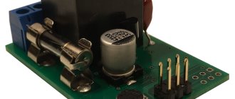
Purpose of drivers for LEDs
The brightness of an LED lamp depends on 2 parameters: the current passing through it and the identity of the characteristics of the semiconductors, since any discrepancy will damage the parts. But modern production is not able to provide completely identical crystal parameters.
The instability of the current in a 220-volt network and the difference in characteristics leads to degradation of the material and combustion of the LED. To avoid this, install a driver.
It converts electric current:
- sets its amplitude;
- straightens - makes it permanent;
- supplies the same current to all elements (slightly less than the maximum level) and prevents their breakdown.
Key Features
The main difference between the driver is that at the input voltage for which it is designed (for example, 140-240 V), it sets the specified current level on the LEDs. In this case, the potential at the output of the device can be any.
It has 3 main characteristics:
- Rated current. It should not exceed the rated value of the LED, otherwise the diodes will burn out or glow dimly.
- Output voltage. Depends on the type of connection of semiconductors and their number. It is equal to the product of the potential drop of 1 element by their number and can vary within wide limits.
- Power. The entire operation of the device depends on the correct calculation of this characteristic. To do this, sum up the powers of all elements and add 20-25% (overload reserve).
For an LED lamp with 10 elements of 0.5 W each, this parameter will be equal to 5W. Taking into account overload, you should choose a 6-7 W driver.
But the last 2 parameters (power consumption and output voltage) directly depend on the emission spectrum of the LED. For example, XP-E elements (red) at 1.9-2.5 V consume 0.75 W, and green ones consume 1.25 W with a power supply of 3.3-3.9 V. It turns out that the driver is 10 W capable of powering 7 diodes of one color or 12 of another.
Power theory for LED lamps from 220 V
An ice lamp, ceiling strip or backlight on a modern TV is a combination of several powerful small LEDs placed in the space in the right way.
To replace a 60 W light bulb (in terms of brightness), you will need about a dozen inexpensive semiconductor devices.
If each of them is capable of passing a current of 1 A at a voltage of 3.3 V, then they cannot be included in the lighting network - they will immediately burn out. You can use a resistor divider, but they will dissipate a lot of power. Therefore, the efficiency of the lamp will be small.
Drivers are used to reduce voltage and convert current into direct current. Inside these devices there may be various current stabilizers, capacitive-resistive dividers, etc.
The circuit may include transistors, microcircuits, capacitors, etc. Such converters change the voltage and provide the required amount of current to each element.
Resistor circuits
This scheme is quite capable even for novice masters. To assemble a device based on it, you need to buy 2 12k resistors, as well as a pair of circuits with the same number of chips soldered in series, taking into account polarity. One strip of diodes on the side (R2) is connected as the anode, and the other (R1) as the cathode. Devices that are assembled according to this scheme are distinguished by a soft light, since at the moment of switching on the LEDs light up one after the other.
Fig. 5 – resistor for an LED lamp.
Thanks to this effect, the naked eye practically does not see the pulsation. This bulb is best suited for a table lamp. To get optimal lighting, it is recommended to purchase strips with 20-40 diodes. If there are fewer of them, it will give an insignificant luminous flux. But the more elements, the more difficult the work is technically.
Types of LED Drivers
There are several types of converters for semiconductor light sources. The main types are linear and pulse. Each of them is created for its own purposes and has its own nuances.
Linear
This type is used often. Its assembly, if all the parts are present, can last 5-10 minutes. It requires almost no adjustment - it starts working right away.
The circuit contains a linear current stabilizer, which can be thought of as a variable resistor controlled by an electronic circuit.
When input voltage is applied, it goes to the regulating element and then to the current control circuit (CT). After this, it appears at the output to which the load is connected. The CT unit checks the current and, depending on this, changes the resistance of the control element.
The disadvantage of such a device is low efficiency.
Pulse
This type of driver is based on a different principle. The regulating element here is the keys with a transformer. When voltage is applied, energy begins to accumulate on the windings (in a magnetic field). The current gradually increases.
As soon as it reaches the desired value, the keys will switch. The stored energy will go into the circuit, and the current will begin to decrease. When the minimum value is reached, the keys will work again and the process will repeat.
LED lamp circuits
Before you start assembling the LED lamp, you need to choose one of the possible schemes. There are several options, they all have their advantages and disadvantages. It also all depends on the purpose of making the lamp. One of the most common schemes includes a diode bridge and 4 LEDs.
LED element
If there is a broken LED lamp in the house, you can take the missing parts from it. But before rearranging any elements, you need to check them for correct operation using a 12V battery. Failed parts should be removed. To do this, you need to take a soldering iron and unsolder the contacts, removing the burnt diodes.
Fig. 3 – finished platform with LED elements.
Do not forget about observing the alternation of cathodes and diodes mounted in series. If 2-3 chips are being replaced, they can be soldered to the same areas where the burnt chips were located. Next, about 10 diodes are installed in a row, observing polarity. You also need to make sure that the soldered ends do not touch each other. Otherwise, it will cause a short circuit when turned on.
Converter circuit with diode bridge
As mentioned above, the circuit includes 4 LEDs connected in different directions. That is why the bridge can transform 220V current into pulsating current. This happens during the transition between 2 sine wave chips.
Fig. 4 – circuit with a diode bridge.
Polarity is lost due to their change. During the assembly process, you need to connect a capacitor to the positive output in front of the bridge. Another one should be behind the bridge. It will perform a smoothing function during voltage drops.
Schemes for a softer glow
If the master is faced with the task of getting rid of flickering, which is characteristic of almost all LED light bulbs, several additional elements need to be included in the circuit. In general, it should include capacitors, resistors and a diode bridge.
To protect the lamp from power surges in the network, a 100 Ohm resistor is installed at the beginning of the circuit, followed by a 400 nF capacitor, then a bridge is mounted, followed by a resistor. The last to be included in the circuit are the LEDs.
How the device works
The main job of the driver is to create a given current value at the output and maintain it. Any scheme of this type consists of several parts:
- network filter that protects the network from interference;
- capacitor-resistor (RC) or transformer unit to reduce voltage;
- diode bridge for rectification;
- current stabilizer.
A device with an RC filter works like this:
- A capacitor in an alternating current network performs the functions of capacitance. Together with the bridge, it forms a voltage divider and reduces it to the desired limit. The resistor in its circuit serves for self-charging.
- The reduced voltage is supplied to the current stabilizer, and from it to the LEDs.
A transformer unit is a device of a key or other type, controlled by a generator. It can be made on specialized microcircuits, high-voltage key transistors, simple elements or on a PWM controller.
This driver works as follows:
- when power is supplied, the bridge straightens it, and it goes to the switches, on which antiphase voltages are created with the help of windings;
- simultaneously with them, the generator is turned on, which generates pulses and starts the driver;
- the keys, turning on alternately, ensure uninterrupted operation of the device through the feedback circuit;
- an alternating voltage appears on the output winding, rectified by a bridge or 1-2 diodes together with electrolytic capacitors;
- Next in the circuit there is a current stabilizer, to which the LEDs are connected.
Characteristics and differences from LED strip power supplies
Instead of a converter, you cannot use a simple power supply designed for the same voltage and current. Although both devices (driver and LED strip unit) perform almost the same function, there are significant differences.
A simple power supply converts voltage and produces direct current. The tape elements connected to it consist of an LED and resistors. There can be many such nodes in a tape.
It is difficult to control the glow of a semiconductor, since it depends on changes in the current value, and it is constant in a given node. To increase or change the brightness in an LED strip, you will have to simultaneously adjust all the resistors, and this is unrealistic.
The driver is a current stabilizer. The LEDs are connected to it in series. Since a regulating element can be inserted into any stabilizer, the brightness of the semiconductors can be freely changed. To do this, you just need to raise or lower the total current value.
Assembly process
First of all, the fluorescent lamp must be disassembled. In this design we are interested in the base with a reflector. This is where all the necessary parts are located, which are combined into an electrical circuit that includes the lamp. It must be disassembled carefully, without damaging those very parts.
Please note that the CFL circuit itself is not suitable for an LED lamp. Therefore it must be disassembled. We will need a fuse from the base; there is no need to remove it from the circuit. Next, a diode will also come in handy, by the way, its brand is 1N4007. You will have to add any electrolyte to the new circuit, the main thing is that its voltage is not lower than 50 volts and its capacity is not less than 100 μF. And one more detail that comes in handy is a 1 µF capacitor with a voltage of 630 volts.
Of course, you will need the LEDs themselves. They can be taken from an LED strip, which is cut into sections containing three LEDs. This segment is powered by a voltage of 12 volts. In general, you will need four pieces of LED strip.
The figure below shows a diagram of the assembly of all parts.
To prevent them from dangling in the base itself, you need to attach them using any adhesive. It would be better if it was super glue. But you need to build a frame under the pieces of LED strip. In principle, it can be any easily bendable dense material. Ideally, it will not be metal or any other conductive structure.
Experienced craftsmen use foam board for such tasks because it is easy to process. It must be rolled into a tube so that the diameter of the extension structure is slightly smaller than the diameter of the base. This is done so that the foam board fits into the base, where it is also glued.
Please note that a homemade 220-volt LED lamp is a base and a base for pieces of LED strip. That is, it turns out that the pieces of tape will be glued to the foam corton from the outside. This will be the luminous part of the lamp itself.
The diagram above clearly shows that the tape segments are connected in series. But in the design they will be located one above the other. By the way, you can increase the number of segments (levels) without any problems. You just have to select the capacitor and electrolyte to match the power of the entire lamp, increasing the capacity.
Making a driver for LEDs with your own hands
If the user has several semiconductor crystals or a backlight line from an old TV, he can independently make a current source for them.
To do this, you should purchase devices and parts or remove radio elements from old equipment. Often the efficiency of self-made devices is much higher than that of industrial designs.
Materials and tools for work
For a homemade simple driver you will need:
- capacitors: simple 0.27 uF at 400 V and 2 electrolytic 500×16 V and 100×16 V;
- resistor 500 kOhm at 0.5 W;
- 4 diodes or a ready-made bridge for 220 V;
- LM317 chip;
- soldering iron with a power of 20-40 W;
- flux and solder (preferably POS type);
- pliers, wire cutters, pliers;.
- multi-core insulated copper conductors with a cross section of 0.35-1 mm²;
- heat shrink tube;
- multimeter or tester;
- insulating tape;
- board for desoldering elements.
Simple driver circuits for a 1 W LED and a powerful one
A classic converter is a combination of an electronic voltage divider and a stabilizer chip. The first node consists of 2 elements (a 0.27 μF capacitor and a 500 kOhm resistor) connected in parallel, to which a bridge of diodes that can withstand the input voltage is connected in series.
To smooth out pulsations, install 2 “electrolytes”. The first of them 500×16 V is soldered immediately after the bridge. Then a current stabilizer is installed. Behind it is a second capacitor 100×16 V.
The L7812 chip is often used as a stabilizer, but this is not entirely the right solution. It is a linear voltage regulating device and can burn out if the current changes.
Connection diagram
It is better to use LM317, LM338 or LM350 microcircuits, which have protection against short circuits and overheating. They can be powered with any voltage 5-35 V. 5-10 LEDs can be connected to the driver.
The connection diagram is simple:
- the plus of the divider goes to the input of the microcircuit (1 output);
- the common wire through the anode of the LED goes to the minus of the radio component (middle leg);
- The LM317 output (pin 3) is also connected there through a current-limiting resistor.
By installing an adjustable resistance instead of the last element, you can change the current strength, i.e., the brightness of the LEDs within certain limits.
If you need to build a powerful spotlight, then the driver will have to be modified:
- it is necessary to increase the supply voltage to 24 V;
- install a stabilizer with the highest current, and of the proposed microcircuits, only LM338 can output 5A.
Due to the high current, it should be installed on a radiator.
How to assemble and configure the driver?
A simple LED converter has few elements. The driver can be assembled on a special board, a piece of plywood, or mounted.
The device does not require adjustment if you take all the specified parts. The main thing is to correctly calculate the current limiting resistor.
What materials are required for manufacturing
To assemble the light bulb you need to buy the following structural elements:
- frame;
- LEDs (separately or mounted on a strip);
- rectifier diodes or diode bridge;
- fuses (if there is a burnt-out unnecessary lamp, they can be removed from it);
- capacitor. The capacity and voltage must correspond to the number of chips and the electrical circuit;
- If you have to make a frame for installing chips, you need to purchase a heat-resistant material that does not conduct current. Metal will not work, so it is better to buy thick cardboard or durable plastic.
Tools for the job will include pliers, a soldering iron, scissors, a holder and tweezers. You will also need liquid nails or glue to mount the LEDs if using cardboard.
Nuances of a driver without a current stabilizer
Many users do not install a microcircuit or other similar component at all. But the absence of a transformer leads to voltage and current ripple.
The brightness of the LEDs also changes. The problem is partially solved by a capacitor installed after the bridge. If the stabilizer is not installed, then the minimum ripple value will be 2-5 V.
The option with a microcircuit will get rid of the problem. Therefore, a driver installed by yourself will not be inferior to foreign analogues in terms of pulsation.
Choosing a lamp housing
You should decide on the case before choosing a circuit. In this case, you can use several options:
- incandescent lamp base;
- self-made device;
- using a housing from a halogen or energy-saving lamp.
Masters prefer the last option, since it is the simplest.
Energy saving lamp housing
It is recommended to make a housing for a DIY LED lamp only if the craftsman has enough experience. In most cases, part of the structure is taken from an energy-saving lamp or incandescent lamp. The burnt-out light bulb should be disassembled and the converter board removed. The scheme is installed in one of the following ways:
- Hide it in the basement. A plastic bottle cap will do.
- Place the diodes in the holes made under the bulb in the lid.
- Place the circuits inside the base. This option has improved heat transfer characteristics. Here the chips are connected through existing holes.
To place the chips, just cut a circle out of thick cardboard or plastic. If the work is done carefully, the device will have an aesthetic appearance.
Base with incandescent lamp
Some craftsmen choose the base of an incandescent lamp to install the circuit, as it has an important advantage: after assembly, the master will not have any difficulties screwing the light bulb into the socket, which will ensure heat exchange.
Fig. 9 – incandescent lamp base.
The base of an incandescent lamp also has its disadvantages. The finished structure will not have a beautiful appearance, and it will also not be possible to make high-quality insulation.
We recommend watching the video: How to assemble an LED lamp with your own hands.
Rules for calculating technical parameters
The performance of any device depends on correctly selected components. Therefore, it is necessary to know how to calculate each element of the driver.
The capacity of the quenching capacitor is determined by the formula:
C(uF) = 3200*I load/√(Uinput²-Uoutput²)
For example, for LEDs with a current of 300 mA:
C(μF) = 3200* 300 /√(220²-24²) = 4.367 μF.
The value of the limiting resistance is directly proportional to the amount of current consumed:
- 500 mA – 2.5 Ohm;
- 250 mA – 5 Ohm;
- 125 mA – 10 Ohm.
Knowing these values, you can calculate the resistor for any number of LEDs.


