Device
In its simplest classical version, a power supply is a transformer that lowers or increases alternating voltage due to electromagnetic induction. If it is necessary to convert the voltage form from alternating (AC) to direct (DC) - an AC-DC power supply, then a voltage rectifier is used. Also, the classic AC-DC power supply contains a ripple filter created by the rectifier.
The classic version is largely justified due to its simplicity, reliability, availability of components and the absence of generated radio interference. But due to the large weight and dimensions, which increase in proportion to power, metal consumption, as well as low efficiency with a stable output voltage, classic transformer power supplies are becoming a thing of the past. They are being replaced by switching power supplies, which will be discussed in detail.
Switching power supplies are an inverter system in which the incoming electricity is first rectified, then converted into a high-frequency current of a certain duty cycle with the amplitude of rectangular pulses, and then converted by a transformer and passed through a low-pass filter. By increasing the efficiency of the transformer with increasing frequency, the requirements for dimensions and metal consumption are reduced compared to classic power supplies.
Switching power supplies have become widespread due to a number of advantages: significantly smaller dimensions and weight with comparable power; much higher efficiency (up to 98%) due to the stability of the key elements - losses occur only when turned on or off; lower cost - this became possible due to the widespread production of the necessary structural elements and the development of high-power transistors; comparative reliability; larger range of input frequencies and voltages - a switching power supply operates equally stably in the range from 110 to 250 volts and at a frequency of 50-60 Hz, which makes it possible to use equipment with switching power supplies everywhere; short circuit safety.
To be fair, it should be said that switching power supplies are not without their drawbacks - difficulty or impossibility of repair, the presence of high-frequency radio interference. Thanks to modern technologies, these disadvantages can be overcome, as evidenced by the wide distribution, popularity and demand of such blocks on the market.
But, thanks to the wide distribution and wide variety of switching power supplies on sale, differing in functionality and characteristics, it is sometimes very difficult to choose the right one. Let's try to understand the main differences between pulse units, their characteristics and features, and also answer the question: what you need to pay attention to if you want to buy a power supply.
Features of the characteristics of switching power supplies
First of all, power supplies are divided by conversion functionality. Some power supplies convert electricity in such a way that the output produces a stabilized voltage at the required power - these are AC-DC power supplies. Others convert electricity so that the output produces a stabilized constant current within specified voltage ranges - these are the so-called drivers.
Switching power supplies
Both power supplies have a certain maximum output power. But, if in the first case the voltage remains constant while the current increases depending on the power of the electricity consumers, then in the second case the current remains constant, and the output voltage changes depending on the power of the consumers. The range of change in drivers is limited, so they are less widely distributed. They are used mainly in lighting engineering, where the required current parameters are known in advance.
Simply put, if you need a power supply with the required current, for example 700mA, at a certain power, then you need to choose a driver. If you need a power source of a given voltage and power, then you need an AC-DC power supply.
When selecting a power supply, it is important to consider its main characteristics. With drivers it’s simpler: everything you need to know about them is usually known within the specifications of the energy consumer. Drivers are found mainly in finished electrical products.
It's a little more complicated with AC-DC power supplies. Modern power supplies may have different output voltage characteristics. As a rule, these are: 5 volts, 12 volts, 24 volts. There are power supplies with other output characteristics: 3.3 volts, 18 volts, 32 volts and others, but they are less common, unlike the first ones, which are popular in outdoor and interior advertising and in decorative lighting. Power supplies are needed, in most cases, to connect LED modules, strips, rulers, and to power other decorative lighting equipment.
Types of power supplies
Depending on the amount of electricity consumed and the power of connected consumers, the power of the power supply is selected. Here it is necessary to take into account that when turning on and off the characteristics of the unit are unstable, and also that during operation the characteristics of the input electricity may change in one direction or another, therefore the unit is selected with a power reserve, which is 1.2 - 1.3 of power of connected consumers. Overloading the unit with power may damage it or cause it to malfunction.
Another important selection criterion when you are going to buy a power supply is the area of its use. This is also true for drivers. The block can be used indoors or outdoors. In the second case, it can be placed on a wall or on a horizontal plane, in the shade or in the sun, it can be exposed to atmospheric influences in the form of snow precipitation and other things, or it can be placed under a roof or canopy. All this affects what degree of IP protection and in what housing to choose a power supply.
For internal use, as well as for placement in closed shields, the best choice would be power supplies with IP20 protection, that is, not waterproof, in a protective casing in the form of a mesh that prevents direct contact with dangerous elements.
When choosing such power supplies, you should pay attention to the presence of an EMI filter - this will avoid or minimize radio frequency interference that occurs during operation of the power supply. Sometimes manufacturers do this in pursuit of a competitive price, so when buying a relatively inexpensive power supply, you should pay attention to this issue.
Interesting material: What is a trim resistor: description of the device and its scope of application
It may also be useful to have an adjustment of the output parameters of current (in the case of drivers) or voltage, that is, the presence of a tuning resistor.
It will be interesting➡ Making a laboratory power supply with your own hands
Sometimes the choice is influenced by the size of the power supply. Currently, you can find power supplies with the same characteristics, but with a large difference in size. Smaller blocks, as a rule, have the definitions compact, slim, extra-slim in their names. Smaller dimensions are achieved due to the development of technology - a denser layout and a more advanced element base.
Often power supplies with IP20 protection have active cooling in the form of a fan that runs constantly or is activated when a certain temperature is exceeded. The convenience of almost all blocks in mesh housings is a sufficient number of screw contacts for connecting consumers.
IP20
For outdoor use, waterproof power supplies are required. Their degree of protection starts from IP53. These are the so-called rain proof blocks or blocks with protection from rain. They represent a compromise between waterproof blocks and “grids”, since they have non-insulated contacts, covered only by a lid, and should only be placed on the wall in a vertical position. They should not be placed in places subject to precipitation.
The next most secure power supplies are made in a plastic or aluminum case and can have a degree of protection IP66-67. They can be placed anywhere, but it is worth considering that plastic is more susceptible to deformation, so in places with direct sunlight, blocks in an aluminum case are preferable. Also, units in plastic cases have power limitations: as a rule, this is a maximum of 150W. In both the plastic and aluminum versions, the power supply is filled with a special compound that ensures tightness and dissipates heat. Waterproof units do not have open contacts; instead, cable-type terminals are used. There may be several of them to ensure the required total cross-section and ease of installation. The outputs are connected to one power bus. Therefore, if necessary, they can be combined.
Power supplies in aluminum cases, as well as grids, can be made in compact, slim or extra-slim sizes. Although, depending on the manufacturer, the name may be different. The point is that it is a smaller block.
Power supplies in aluminum
When buying a power supply, you also need to pay attention to other features. PSU manufacturers may offer different protection options, which may affect the price of the power supply, but one or another option may be useful. All modern units have short circuit protection. Overload protection can be useful, for example, Mean Well offers protection such as Hiccup mode - when overloads occur, the power supply switches to a rare pulsation mode to avoid overheating until the overload characteristics return to normal. In some cases, the color of the power supply is critical - it may not necessarily be white or metallic. There are black power supplies - this is suitable for those places where the light color of the unit catches the eye.
There are many features and characteristics, but they are not as difficult to understand as it seems at first glance. Knowing these features and being guided by the necessary characteristics, you can easily select and buy a power supply that is best suited for your goals and objectives.
Assembling an adjustable power supply
Those beginners who are just starting to study electronics are in a hurry to build something supernatural, like microbugs for wiretapping, a laser cutter from a DVD drive, and so on... and so on... What about assembling a power supply with an adjustable output voltage? This power supply is an essential item in every electronics enthusiast's workshop.
Where to start assembling the power supply?
First, you need to decide on the required characteristics that the future power supply will satisfy. The main parameters of the power supply are the maximum current (Imax) that it can supply to the load (powered device) and the output voltage (Uout), which will be at the output of the power supply. It is also worth deciding what kind of power supply we need: regulated or unregulated.
A variable power supply is a power supply whose output voltage can be varied, for example, between 3 and 12 volts. If we need 5 volts - we turned the regulator knob - we got 5 volts at the output, we need 3 volts - we turned it again - we got 3 volts at the output.
Adjustable power supply
An unregulated power supply is a power supply with a fixed output voltage - it cannot be changed. For example, the well-known and widely used “Electronics” power supply D2-27 is unregulated and has an output voltage of 12 volts. Also unregulated power supplies are all kinds of chargers for cell phones, adapters for modems and routers. All of them, as a rule, are designed for one output voltage: 5, 9, 10 or 12 volts.
It is clear that for a novice radio amateur it is the regulated power supply that is of greatest interest. It can power a huge number of both homemade and industrial devices designed for different supply voltages.
Next you need to decide on the power supply circuit. The circuit should be simple, easy to repeat by beginning radio amateurs. Here it is better to stick to a circuit with a conventional power transformer. Why? Because finding a suitable transformer is quite easy both in radio markets and in old consumer electronics. Making a switching power supply is more difficult. For a switching power supply, it is necessary to produce quite a lot of winding parts, such as a high-frequency transformer, filter chokes, etc. Also, switching power supplies contain more electronic components than conventional power supplies with a power transformer.
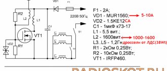
So, the circuit of the regulated power supply proposed for repetition is shown in the picture (click to enlarge).
Power supply parameters:
- Output voltage (Uout) – from 3.3...9 V;
- Maximum load current (Imax) – 0.5 A;
- The maximum amplitude of output voltage ripple is 30 mV;
- Overcurrent protection;
- Protection against overvoltage at the output;
- High efficiency.
It is possible to modify the power supply to increase the output voltage.
The circuit diagram of the power supply consists of three parts: a transformer, a rectifier and a stabilizer.
Transformer. Transformer T1 reduces the alternating mains voltage (220-250 volts), which is supplied to the primary winding of the transformer (I), to a voltage of 12-20 volts, which is removed from the secondary winding of the transformer (II). Also, “part-time”, the transformer serves as a galvanic isolation between the electrical network and the powered device. This is a very important function. If the transformer suddenly fails for any reason (voltage surge, etc.), then the mains voltage will not be able to reach the secondary winding and, therefore, the powered device. As you know, the primary and secondary windings of a transformer are reliably isolated from each other. This circumstance reduces the risk of electric shock.
Rectifier. From the secondary winding of power transformer T1, a reduced alternating voltage of 12-20 volts is supplied to the rectifier. This is already a classic. The rectifier consists of a diode bridge VD1, which rectifies alternating voltage from the secondary winding of the transformer (II). To smooth out voltage ripples, after the rectifier bridge there is an electrolytic capacitor C3 with a capacity of 2200 microfarads.
Adjustable switching regulator
The switching stabilizer circuit is assembled on a fairly well-known and affordable DC/DC converter microcircuit - MC34063.
It will be interesting➡ What is an integrated circuit
To make it clear. The MC34063 chip is a specialized PWM controller designed for pulsed DC/DC converters. This chip is the core of the adjustable switching regulator used in this power supply.
The MC34063 chip is equipped with a protection unit against overload and short circuit in the load circuit. The output transistor built into the microcircuit is capable of delivering up to 1.5 amperes of current to the load. Based on the specialized MC34063 chip, you can assemble both step-up and step-down DC/DC converters. It is also possible to build adjustable pulse stabilizers.
Features of pulse stabilizers
By the way, switching stabilizers have a higher efficiency compared to stabilizers based on microcircuits of the KR142EN series (KRENKI), LM78xx, LM317, etc. And although power supplies based on these microcircuits are very simple to assemble, they are less economical and require the installation of a cooling radiator .
Efficiency
The MC34063 chip does not require a cooling radiator. It is worth noting that this chip can often be found in devices that operate autonomously or use backup power. The use of a switching stabilizer increases the efficiency of the device, and, consequently, reduces power consumption from the battery or battery. Due to this, the autonomous operating time of the device from a backup power source increases.
I think it’s now clear why a pulse stabilizer is good.
Current-voltage converter
A current-voltage converter implemented on a dual operational amplifier LM358N is connected to the output of the stabilizer. The circuit diagram of this converter can be found in the documentation for this microcircuit; you can read about it in “Radio” for 2002. No. 9 p.23. And Nechaev, or on my website in the article “Microcircuits for measuring current.” This circuit is good because it eliminates the need to adjust the resistance of the current sensor, i.e. shunt. The current converter is assembled on one of the op-amps of the DA2 LM358N chip, R7 is a current sensor, C7 smoothes out the shape of the measured current at large ripples. The resistor values are chosen in such a way that when a current of 1 A flows through the shunt, the voltage across resistor R6 will drop 1 volt. The magnitude of this voltage, i.e. the conversion coefficient is regulated by resistor R5. From this resistor R6 you can remove and digitize a signal for an ammeter. Capacitor C5 also serves as a filter capacitor, otherwise false triggering of the protection circuit is possible. If a digital ammeter is used, the information on the indicator will be difficult to analyze. The second half of the DA2 chip contains a comparator for the stabilizer protection circuit .
Parts and electronic components
Now a little about the parts that will be required to assemble the power supply.
Transformer. Any network step-down transformer with a power of 8-10 watts is suitable as a transformer. Its primary winding (I) should be designed for an alternating voltage of 220-250 volts, and the secondary (II) for 12-20 volts.
Where can I find such a transformer?
You can find a suitable transformer in old, faulty and obsolete equipment: cassette recorders, stationary CD players, game consoles, etc. For example, transformers from old Soviet-made tube-semiconductor TVs TVK-110LM, TVK-110L2 and TVK-70 are suitable. You can purchase a transformer of the TP114 series, for example TP114-163M. When selecting a power transformer, it will not be amiss to have an idea of how to find out the power of the transformer.
A TS-10-3M1 transformer with an output voltage of about 15 volts is also suitable. You can find a suitable transformer in radio parts stores and radio markets, the main thing is that it meets the specified parameters.
Chip MC34063. The MC34063 is available in DIP-8 (PDIP-8) for conventional through-hole mount and SO-8 (SOIC-8) for surface mount. Naturally, in the SOIC-8 package the chip is smaller in size, and the distance between the pins is about 1.27 mm. Therefore, it is more difficult to make a printed circuit board for a microcircuit in the SOIC-8 package, especially for those who have only recently begun to master printed circuit board manufacturing technology. Therefore, it is better to take the MC34063 chip in a DIP package, which is larger in size, and the distance between the pins in such a package is 2.5 mm. It will be easier to make a printed circuit board for a DIP-8 package.
Diode bridge. The diode bridge for the power supply can be made from 4 separate diodes 1N4001-1N4007. Also, instead of 1N4001-1N4007 diodes, you can use 1N5819 diodes. At the same time, the efficiency of the power supply will increase, since the diodes of the 1N58xx series are Schottky diodes and they have a lower voltage drop across the pn junction than conventional diodes of the 1N400x series.
You can also install a bridge rectifier diode assembly into the power supply. The assembly takes up less space on the printed circuit board. Assemblies with a current of 1 ampere and higher are suitable for installation in a circuit. For reliability, you can plug an assembly into the board at 2 amperes - it won’t be any worse.
Where can I find a diode bridge assembly? In used boards from any electronics that is powered by a 220 volt network. Even compact fluorescent lamps - CFLs - have a diode bridge. You can pick it out from there. The truth is that you will come across 4 separate diodes or a diode bridge assembly, you can only guess - how lucky you will be.
To be more specific, the following diode bridges (assemblies) are suitable: DB101-107, RB151-157, D3SBA10, 2W10M, DB207, RS207 and others similar and more powerful. You can easily use a diode bridge from a faulty computer power supply. They are powerful and healthy, designed for quite a large current - enough for the eyes. Don't forget to check it for serviceability!
Capacitors C1, C2, C4, C5 are used to suppress impulse noise that comes from the power supply. In addition, they block impulse noise that can enter the power grid from the impulse stabilizer itself.
Elements of protection. The circuit uses two fuses. Fuse FU2 is a conventional fuse with a trip current of 0.16 A (160 mA). It is connected in series with the primary winding (I) of transformer T1. FU1 is a self-resetting fuse. When the current through it becomes more than 0.5 amperes, its resistance increases sharply, and the current in the rectifier and stabilizer circuits drops sharply.
This provides protection in the event of a converter failure. Zener diode VD3 also serves as a protective diode and is paired with a self-restoring fuse FU1. Its main purpose is to protect the load (powered device) from damage by high voltage. The stabilization voltage of the zener diode is 11 volts. If the converter malfunctions and a voltage of more than 11 volts appears at the output, the current through the zener diode increases sharply. The increased current in the circuit causes fuse FU1 to trip, which limits the current. Therefore, the protective zener diode VD3 must be installed in the circuit. If it is not possible to find a suitable self-resetting fuse, it can be replaced with a conventional fuse with an operating current of 0.5 amperes.
List of parts needed to assemble the power supply.
| Name | Designation | Rating/Parameters | Brand or item type |
| Chip | DA1 | MC34063 | |
| Diode bridge | VDS1 (VD1-VD4) | 1-2 amps, 600 volts | D3SBA10, RS207, DB107 and analogues |
| Electrolytic capacitors | C8, C9, C12 | 330 uF * 16 volts | K50-35 or analogues |
| C3 | 2200 uF * 35 volts | ||
| Capacitors | C1, C2, C4, C5, C10, C11, C13 | 0.22 µF | KM-5, K10-17 and similar |
| C6 | 0.1 µF | ||
| C7 | 470 pF | ||
| Resistors | R1 | 0.2 Ohm (1 W) | MLT, MON, S1-4, S2-23, S1-14 and similar |
| R3 | 560 Ohm (0.125 W) | ||
| R4 | 3.6 kOhm (0.125 W) | ||
| R5 | 8.2 kOhm (0.125 W) | ||
| Variable resistor | R2 | 1.5 kOhm | SP3-9, SP4-1, PPB-1A and similar |
| Schottky diode | VD2 | 1N5819 | |
| Zener diode | VD3 | 11 volts | 1N5348 |
| Throttle | L1, L2 | 300 µH | |
| Throttle | L3 | homemade | |
| fuse | FU2 | 0.16 ampere | |
| Self-resetting fuse | FU1 | 0.5 ampere (for voltage >30-40 volts) | MF-R050; LP60-050; FRX050-60F; FRX050-90F |
| LED indicator | HL1 | any 3 volt |
Chokes. Chokes L1 and L2 can be made independently. To do this, you will need two ring magnetic cores made of 2000HM ferrite, size K17.5 x 8.2 x 5 mm. The standard size is deciphered as follows: 17.5 mm. – outer diameter of the ring; 8.2 mm. - inner diameter; a 5 mm. – height of the ring magnetic circuit. To wind the choke you will need a PEV-2 wire with a cross section of 0.56 mm. 40 turns of such wire must be wound on each ring. The turns of the wire should be distributed evenly over the ferrite ring.
Chokes L1 and L2
Before winding, the ferrite rings must be wrapped in varnished cloth. If you don’t have varnished fabric at hand, you can wrap the ring with three layers of tape. It is worth remembering that ferrite rings may already be painted - covered with a layer of paint. In this case, there is no need to wrap the rings with varnished cloth.
It will be interesting➡ What is the element base and where is it used
In addition to homemade chokes, you can also use ready-made ones. In this case, the process of assembling the power supply will speed up. For example, as chokes L1, L2 you can use the following surface-mount inductors (SMD - inductor).
As you can see, on the top of their case the inductance value is indicated - 331, which stands for 330 microhenry (330 μH). Also, ready-made chokes with radial leads for conventional installation in holes are suitable as L1, L2. This is what they look like.
The amount of inductance on them is marked either with a color code or with a number. For the power supply, inductances marked 331 (i.e. 330 μH) are suitable. Taking into account the tolerance of ±20%, which is allowed for elements of household electrical equipment, chokes with an inductance of 264 - 396 μH are also suitable. Any inductor or inductor is designed for a certain direct current. As a rule, its maximum value (IDC max) is indicated in the datasheet for the inductor itself. But this value is not indicated on the body itself. In this case, you can approximately determine the value of the maximum permissible current through the inductor based on the cross-section of the wire with which it is wound. As already mentioned, to independently manufacture chokes L1, L2, you need a wire with a cross-section of 0.56 mm.
Throttle L3 is homemade. To manufacture it, you need a magnetic core made of ferrite 400HH or 600HH with a diameter of 10 mm. You can find this in antique radios. There it is used as a magnetic antenna. You need to break off a piece 11 mm long from the magnetic circuit. This is quite easy to do; ferrite breaks easily. You can simply tightly clamp the required section with pliers and break off the excess magnetic circuit. You can also clamp the magnetic core in a vice, and then sharply hit the magnetic core. If you fail to carefully break the magnetic circuit the first time, you can repeat the operation.
Then the resulting piece of magnetic circuit must be wrapped with a layer of paper tape or varnished cloth. Next, we wind 6 turns of PEV-2 wire folded in half with a cross-section of 0.56 mm onto the magnetic circuit. To prevent the wire from unwinding, wrap it with tape on top. Those wire leads from which winding of the inductor began are subsequently soldered into the circuit in the place where the points are shown in image L3. These points indicate the beginning of winding the coils with wire.
Add-ons
Depending on your needs, you can make certain changes to the design.
For example, instead of a VD3 zener diode type 1N5348 (stabilization voltage - 11 volts), you can install a protective diode - a 1.5KE10CA suppressor - into the circuit.
A suppressor is a powerful protective diode, its functions are similar to a zener diode, however, its main role in electronic circuits is protective. The purpose of the suppressor is to suppress high-voltage pulse noise. The suppressor has a high speed and is able to extinguish powerful impulses.
Unlike the 1N5348 zener diode, the 1.5KE10CA suppressor has a high response speed, which will undoubtedly affect the performance of the protection.
In technical literature and among radio amateurs, a suppressor can be called differently: protective diode, limiting zener diode, TVS diode, voltage limiter, limiting diode. Suppressors can often be found in switching power supplies - there they serve as protection against overvoltage of the powered circuit in the event of faults in the switching power supply.
You can learn about the purpose and parameters of protective diodes from the article about the suppressor.
The 1.5KE10CA suppressor has the letter C in its name and is bidirectional - the polarity of its installation in the circuit does not matter.
If there is a need for a power supply with a fixed output voltage, then the variable resistor R2 is not installed, but replaced with a wire jumper. The required output voltage is selected using a constant resistor R3. Its resistance is calculated using the formula:
Uout = 1.25 * (1+R4/R3)
After the transformations, we obtain a formula that is more convenient for calculations:
R3 = (1.25 * R4)/(Uout – 1.25)
If you use this formula, then for Uout = 12 volts you will need a resistor R3 with a resistance of about 0.42 kOhm (420 Ohm). When calculating, the value of R4 is taken in kilo-ohms (3.6 kOhm). The result for resistor R3 is also obtained in kilo-ohms.
To more accurately set the output voltage Uout, you can install a trimming resistor instead of R2 and set the required voltage using the voltmeter more accurately.
It should be taken into account that the zener diode or suppressor should be installed with a stabilization voltage 1...2 volts higher than the calculated voltage at the output (Uout) of the power supply. So, for a power supply with a maximum output voltage equal to, for example, 5 volts, you should install a suppressor 1.5KE6V8CA or similar.
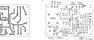
PCB manufacturing
A printed circuit board for a power supply can be made in different ways. Two methods for making printed circuit boards at home have already been discussed on the pages of the site.
- The fastest and most comfortable way is to make a printed circuit board using a printed circuit board marker. The Edding 792 marker was used. It showed its best side. By the way, the signet for this power supply was made with just this marker.
- The second method is suitable for those who have a lot of patience and a steady hand. This is a technology for making a printed circuit board using a correction pencil. This is a fairly simple and affordable technology that will be useful to those who could not find a marker for printed circuit boards, but do not know how to make boards with LUT or do not have a suitable printer.
- The third method is similar to the second, only it uses tsaponlak - How to make a printed circuit board using tsaponlak?
In general, there is plenty to choose from.
Operation of the stabilizer circuit
The DA1 chip includes a voltage stabilizer, a reference voltage source (pin 8), a mismatch amplifier (input pin 6) and an on/off pin for the stabilizer, pin 9 of the DA1 chip. Moreover, in the off state, the output voltage of the stabilizer, at least for me, is only 4 mV. The inclusion of the stabilizer in this circuit is ensured by the RC circuit R2, C2. When voltage appears at the input of the stabilizer, capacitor C2 begins to charge, the charging current creates a voltage drop between pins 9 and 7 of the DA1 microcircuit, this voltage is enough to turn on the stabilizer. In general, it should be at least two volts. The output voltage is set using trimming resistor R4.