An alternative list with cheaper components from Aliexpress is here. This is not a new article, but an old one, just updated today, i.e. September 15, 2014. Due to changes in the rules for the delivery of lithium-polymer batteries, cost calculations are no longer relevant. Plus, I took into account the experience I had gained over these two years.
So. If you managed to glue the plane together and you liked the result, it’s time to start thinking about the electronic filling. And remember that when buying electronics for the LM-17, you are simultaneously buying it for other aircraft. True, for this you will need to disassemble the LM-17... although I suspect that this will happen, sooner or later (I’m talking about the accident). Especially without training. Although, to be honest, you don’t need to follow my example and get used to accidents; it’s better to first practice in the simulator. And by the way, this also requires electronics, and more specifically radio equipment and a connection cord to a PC.
Very optimal equipment for beginning aircraft modellers. Six channels, of which we will use only 3, the biplane has 4 (and we will not use the 5th and 6th soon). Includes both transmitter and receiver.
When I ordered it, it came complete with a PC connection cable. But the website says that now it comes without it. The cable is needed to configure this equipment (and we will use it, so the cable is NEEDED). In addition, it can be used for training in the RealFlight simulator (I really don’t recommend it, a separate one is better).
- Cable for connecting radio equipment to PC. (required!)
- Cable for RealFlight simulator. Significantly simplifies the connection of equipment to the simulator. I couldn’t stand the torment with the standard cable (I still need it to set up the equipment) and bought this cable. As you wish. In principle, you can train with a regular one. Moreover, there are other flight simulators, including free FMS.
An interesting option is this five-channel Turnigy 5x equipment. Small, light, cheap (even in terms of delivery). Allows you to change the reverse settings directly in the field, supports the “elevon” mode - i.e. you can control the flying wing. The downside is that there are some difficulties connecting it to the simulator, but I’m working on it. And perhaps someone has already found a solution, you can try searching (I always prefer to go “my way”). Of course, the above cables are not needed for it.
Here you can choose (depending on stock availability). You need at least 3 pieces. Or better yet, 5. One for the elevator, one for each console, one for the rudder of the future biplane from the ceiling and one more spare.
- HXT900 (9g micro servo)
- Microservo Turnigy TG9e 9g / 1.5kg / 0.10sec
- Digital Servo HKSCM9-6
Our servos will be quite far from the receiver. Therefore, we will need servo extensions. The set will include 5 pieces 42cm long. For those who know how to solder, you can buy a wire (this one, or this one - there are others) and servo connectors (one and two options, the first is preferable, since it has some protection against incorrect connection), and make a servo extension cord or servo splitter as needed.
Aircraft modeling
Model airplane construction is a popular technical sport that is of interest to schoolchildren, students, workers and engineers. At the same time, everyone chooses for themselves a class of aircraft models that suits their interests.
In aircraft modeling there are three fairly large groups of aircraft models, presented in the table:
| Model class | Peculiarities |
| In such models, designer intervention is impossible during flight. All adjustments and settings of the aircraft are completed when it is launched. They can be: - motorless - gliders; - with a simple, very small, internal combustion engine, which is attached to the body with an elastic band. The motors on the models work for a few seconds to throw the light-winged structures up to a hundred meters up, and then they smoothly go down. Timers or special clock mechanisms are used to turn off the engine and switch the steering wheel to planning. | |
| With such models, the athlete controls wire threads, which are called cord. The devices fly in a circle with a diameter of approximately 40 meters. The “pilot” is located in its center with the control stick. When you pull the handle towards yourself, the elevator deflects, and the device obediently flies up, and deflecting the handle away from you causes the model to descend. The devices are:
| |
| Controlled remotely, wirelessly. For this purpose, there is a set of radio equipment, which includes a transmitter, in the hands of the operator, and a receiver with steering control mechanisms, mounted on board the model. |
Model aircraft structure
Tip: Before you make an airplane from ceiling tiles, you need to become familiar with its design.
The design of all models is very similar. The main components of the radio-controlled airplane model are shown in the photo.
This:
- Fuselage
. This is the basis of the entire model on which the following are mounted:
- bearing structures;
- tail section;
- chassis.
Installed inside:
- engine;
- aircraft control equipment: receiver, steering controls, batteries.
- Wing.
Serves to create lifting force. The wing keeps the model in the air. - Ailerons
are control surfaces located at the rear end of the wing and deflect up or down in antiphase. They allow the plane to tilt left and right. - Tail unit
. It consists of a vertical part - the keel, and a horizontal part - the stabilizer. This device provides stability to the aircraft so that it can fly straight and level without tumbling in the sky, randomly changing the direction of its movement.
The rudder is installed at the rear end of the keel.
- Chassis
. Allow the model to take off from the surface and then land on it.
Advice: If there is no landing gear, the model should be launched by hand, and the plane should be landed “on its belly”.
- Engine
. Creates the movement of the model, allows it to gain the desired height, and then maintain a given speed. - Buck
. Serves for the fuel needed to run the engine.
- Receiver
. Receives the transmitter signal, amplifies it, processes it and transmits it to the steering gears. - Steering cars
. The signal coming from the receiver is converted into moving the model's rudders through the connected rods. - The receiver and machine are powered by an on-board battery
. Usually these are four “finger” elements.
Crossplane - do-it-yourself aircraft model from a ceiling
In this article, we will look at how you can make a so-called Crossolet aircraft model with your own hands.
The peculiarity of this model is that there is no need to glue a wooden or carbon stringer along the fuselage. The load here will go to the transverse bending, which goes to the horizontal part of the fuselage. The model is assembled classically, from the ceiling. The crossplane is the same plane whose fuselage is made in the form of a cross, if you consider the model from the front.
Before you start creating a model, you can read how to attach steering planes. Here you can see how homemade hinges for a model aircraft are made - 8 types to choose from. And here you can learn how to hang ailerons on tape. If you are still a beginner and don’t know what adhesives are used in modeling, you can read about it here.
You can learn about making homemade rods and clamps in this article. If you decide to make hogs with your own hands, then here is a good guide.
You can download the aircraft model drawing from the link: here
Materials and tools for homemade work: - ceiling tiles; - scissors, stationery knife; - scotch; - glue; - paper; — engine with propeller; — battery; — electronics for control; — servomotors; - soldering iron, etc.
Model making process:
Step one. Print and cut out the drawing
The main work of creating an airplane model comes down to cutting out the necessary parts. To do this, the drawing is first printed on paper, and then glued to the ceiling and cut out. Abroad, instead of a ceiling, it is customary to use depron with a thickness of 6 mm, but in our case it can be replaced with a substrate for laminate or isopolin with a thickness of 6 mm. If you use a ceiling, then it should be two-layer.
According to the author, a ceiling model will be stronger and will better withstand bending loads. Among other things, strength will increase thanks to the glue that will be located between the two layers of the ceiling.
Step two.
Connecting the blanks First of all, the fuselage is assembled in order to accurately connect all the parts; they have special cutouts and grooves.
Everything is connected with glue. To give the wing a profile, it needs to be depressed. There is no need to overdo it with strength and depth, as the rounding will be small. When the wing profile is ready, it can then be inserted into the fuselage cutout. Step three.
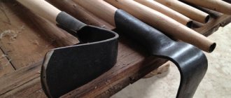
The final stage of assembly Since the author is assembling a half-copy, the wing will need to be given a V. To make the V angle the same for each wing console, stands need to be made under the edges of the wings.
Light plywood linings need to be glued to the bottom of the fuselage. Thanks to these pads, the plane will land successfully without damage, since it does not have landing gear.
As for fastening the hogs and steering rods, they are installed using classical methods. The easiest way is to hang the steering planes on tape.
To secure the engine, a motor mount is made from the ceiling, then another wooden motor mount is installed on this motor mount, and then the engine is installed on it.
Servos are installed in cutouts provided in the fuselages. They can be secured with a heat gun or other glue. Before gluing, you need to wrap the servo with tape so that the glue does not stick together important parts and does not get inside the machine.
The electronic equipment is located in the horizontal part of the fuselage under the wing. That's all, now the model can be tested.
Using this technology, it is also possible to make a version with two frame-type engines. An example of such a model can be seen in the photo.
Source
Become the author of the site, publish your own articles, descriptions of homemade products and pay for the text. Read more here.
Model selection
Advice: When choosing to make an airplane from ceiling tiles with your own hands, you need to ensure, first of all, that it is reliable to take off and land, and then that it satisfies aesthetic needs.
The aircraft model must have the following properties:
- Be stable: stay in the air well without much input from the pilot.
- It is easy to repair, which is ensured by aircraft models made from ceiling tiles.
- Sufficient strength, but without compromising flight qualities: withstand hard landings and fly well.
We do it ourselves
To work you will need tools and materials:
Making any design, including an aircraft model, with your own hands begins with the development of drawings. To do this, you can use the services of specialists or copy them from special sites, print templates on a printer or draw them according to size.
After the printer:
- Printouts on A4 sheet formats are laid out on a flat surface according to serial numbers. The result should be a life-size image of the aircraft elements.
- All the necessary sheets are glued together.
- When gluing sheets without disturbing the dimensions and geometry of the future aircraft, excess edges are cut off on each sheet of the drawing.
- Cutting lines are drawn by connecting special crosses drawn at the corners that define the boundaries of the image.
- The resulting airplane drawings from ceiling tiles are combined with structural fragments, glue is applied to the uncut edges of the sheets, and all parts are carefully glued together so that their joints coincide very precisely.
- This way all the fragmented elements of the model are glued together.
- Paper templates are cut out with scissors.
Manufacturing of blanks
Blanks for assembling the aircraft are cut from ceiling tiles using prepared templates.
Tip: To prevent the sheets from moving from the tiles, they must be fixed to the surface of the material with glue. After marking is completed, the glue does not have time to dry and the paper is easily removed without damage for further use.
- To mark a simple part with straight lines, it is enough to pierce all its corners with a needle.
- Remove the stencil and, using a ruler from adjacent puncture points on the tile, cut through the material with the tip of a knife.
- The ruler is shifted to the next adjacent points until the complete cutting of the part is completed.
- A workpiece of complex shape with rounded sides can be completely cut out according to the template.
- It is advisable to mark each part to facilitate its purpose, according to the assembly drawing.
Airplane assembly
Before you start assembling all the parts, it is better to watch the video.
The aircraft assembly technology can be roughly described as follows:
- Double partitions consisting of several parts are glued together, which increases their strength. For example, fuselage partitions.
Tip: For work you should use Titan glue, its price is the most affordable for beginning modelers. It is more convenient to apply glue with a syringe without a needle, using it as a dispenser.
- To ensure that the ends of the cut parts are smooth, they are sanded with sandpaper.
- The side of the fuselage is placed on the table so that the front side is towards the outside of the aircraft. All mounting holes are cut out on it.
- Using this part, the same holes are made on the second half of the fuselage.
- Glue is applied to the glued side of the front compartment partition blank and the part is pressed into place at the installation site. After spreading the composition on the mating part, the workpieces are separated and left for the glue to partially dry for about 30 seconds. The parts are connected again and pressed with force for about 10 seconds.
- When assembling an aircraft, it is necessary, if necessary, to adjust the dimensions of the battery compartment, constantly checking with a square or ruler the perpendicularity of the parts being joined.
- This is how all the fuselage partitions are gradually assembled.
- After installing all the partitions, the second side of the fuselage is glued.
- The nose of the aircraft and the mounting of the frame for the engine are being completed.
- The upper part of the fuselage is installed.
- The tail blanks are glued together. In this case, reinforced tape fittings are immediately laid to fix the rudder and toothpicks for rigidity.
- The gluing is clamped with a board and clamps, which will ensure evenness of gluing.
- The tail is glued into place.
- The verticality of the elements is controlled and strictly maintained.
- The elevator parts are glued together. In this case, a bamboo skewer and tape are placed inside to fix the steering wheel. To ensure reliable gluing of the ceiling halves, the tape can be perforated with holes.
- The elements are compressed with a board and clamps, and left for about a day until the glue dries completely.
- The edges are ground down with sandpaper or a stone at an angle of 45°, which will allow them to not rest against each other when the planes of the model are tilted.
- The wing is assembled, lines are marked on it for gluing stiffeners, ribs, and spars.
- A wooden axle or spar can be made from a wooden ruler 50 centimeters long.
- The spar rail is glued.
- The joint in the center is reinforced with two small slats.
- Foam plastic neurites are glued in.
- The desired shape of the wing plane is set. To do this, the substrate or ceiling material is rolled onto a piece of pipe.
- Glue is applied to all mating elements and final gluing is performed. While the adhesive composition is setting, the wing is fixed in any available way: weights, clothespins, tape.
- Small dents caused by clothespins are sanded with sandpaper.
- The cavities in the center of the wing are closed and inserts are glued.
- After the glue has dried, the ailerons are marked. In this case, it is necessary to additionally look at the assembly in the light so as not to get on the partition.
- They are cut through on both sides with a cutter, and the finished aileron is removed.
- Opened cavities are sealed with strips of tiles.
- The ailerons can be glued immediately with reinforced tape or later, before the main covering of the aircraft model with tape.
- The front part of the wing can be reinforced with reinforced tape.
- The entire model is covered with tape, which serves for beauty, and most importantly gives the structure greater strength, which will allow the model to withstand impacts from falling.
- The adhesive tape is smoothed with a warm iron, which will finally attach it to the ceiling tiles.
- A slot is made in the body of the aircraft into which the wing is installed.
- Servos are installed on the wing. To do this, the elements are applied and outlined with a marker, and a seat is cut out.
- The wires are pulled with a homemade wire hook.
- On the contrary, hogs are installed on the ailerons and connected to the servos with a rigid wire.
- Two servos are installed in the aircraft fuselage, for the rudder and elevator. For fixation, it is better to use double-sided tape, glued to all contact areas of the servo.
- The elements are installed in place and the supporting walls are additionally glued. The rods are laid from rigid wire to the rudders.
- A frame is made to mount the motor.
- Thin plywood is glued to the motor mounting side; bolts will be screwed into it to secure the motor.
- The frame for the motor is glued into place.
- The motor driver is mounted in front of the fuselage; wires are brought out through the ventilation window and connected to the wires from the motor.
- The direction of rotation is checked.
- The fairing is put in place and secured with tape.
- To strengthen the installation site of the wing, it must be reinforced by gluing plywood or thin shingles.
- The receiver is installed, and all the wires from all the electronics are collected together.
- The bottom of the fuselage is glued, a hatch is cut for mounting the battery.
- The total weight of the model is approximately 450 grams.
- You can fly over a model airplane. The video will show you how to do this.
Assembling airplanes from ceiling tiles is the simplest option, which a novice aviation enthusiast can do if desired. The main condition is to do everything carefully, adhering to the assembly technology, and it is better to take the advice of a specialist.
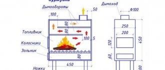
Power plant (motor, battery, governor, propeller)
We will have a spare power plant. A very large reserve, this will allow us to later assemble other aircraft on its basis, a little more complex and larger (for example, a biplane, also from the ceiling).
Motor characteristics:
- Maximum current: 7A
- Traction: 500-600 grams
- Rotation speed: 1500 rpm at 1V . (at 11.1 volts we get 16 thousand rpm.
The motor comes with a propsaver (propeller protection, more on that later). There are no connectors on the motor wires - you will have to solder them later (also later).
or ZIPPY Compact 1000mAh 3S 35C Lipo Pack
Battery characteristics (for 1000mAh!):
- Battery weight: 92g
- Rated discharge current: (Rating) 35C , i.e. 35*1.0 = 35 amperes. More than enough. By the way, the maximum current is 45C = 45 amperes. This means that you will receive this current (and maybe even more, because 45 is the standard maximum) by accidentally short-circuiting the battery. At best, this current will damage your connectors with a powerful spark (or burn the wires). And in the worst case, this current will very quickly (in tens of seconds) heat your battery to an explosive state... and the battery will explode. And I'm not joking or exaggerating. We will still talk about safety precautions when handling lithium-polymer batteries, but that’s just me - I’m scaring you in advance. However, 1.0Ah is not much. 8A with a rating of 45C (360A!) - this is really scary
- Voltage: 11.1 volts. But it is different for a discharged and charged battery. Three banks with voltage from 3.3 (lower is still not necessary) to 4.2 volts. This means from 10 to 12.6 volts.
- Capacity: 1000 mAh. At maximum speed at 7A, this will be 9 minutes. Let's take into account that we will have a not very standard propeller for this motor (but tested many times in practice), which will take a little more current. Let’s also take into account that you won’t fly at full thrust - otherwise you’ll quickly crash the plane. It's really interesting to fly at 40-50% thrust. Those. The battery will last for about 20-22 minutes of flight (taking into account the moments where you will give full thrust). Believe me, this is more than enough for the first flights.
Now on my LM-15 with this motor and regulator I use a three-cell 2200mAh battery with a rating of 20C. The flight time is quite significant, although for the LM-17 I do not recommend this battery, since with such an increase in weight it will fly very quickly (which is not good for a beginner).
8040 is the encrypted diameter and pitch of the propeller. Another common name is 8x4. Means the following:
- diameter - 8 inches (8*2.54=203 mm).
- pitch - 4 inches (the pitch of the screw is the distance it travels when screwing it into a hard surface a full turn. Depends on the angle of the blades)
The set will include 6 propellers. In case of an accident, even with a propsaver, they often break. It might make sense to order 2 sets. By the way, they are not actually orange, but black. Look on the website - there are other colors there (search string “8040″ or “8×4″, without quotes, of course). It might make sense to take a bright color so that you can easily find it later if it suddenly falls off in an accident.
You can also try the faster 7060 propeller. Be careful with them, the edges are very sharp. Less thrust, but more speed. The LM-2, for example, is much more enjoyable to fly with.
Yes, still. Propellers with the same diameter and pitch have different rotation speeds. We need high-speed propellers. Don't even think of putting propellers with the letters SF in the name (for slow flights) or RD (for motors with gearboxes).
Characteristics:
- Rated current: 12A (we have 7-9A maximum for the motor, if you still want a larger current reserve, then here is a more powerful one (a little more expensive)
The regulator comes without connectors included. They will have to be bought and soldered.
- For connection to battery. These or these with ready-made soldered wires (2 times more expensive, but you won’t have to suffer, but just solder the wires). The set will include 5 pieces. And although we only need 1, there’s nothing we can do about it. Well, there will be spare ones. Attention! If you chose a different battery with a different type of connector, then these connectors will not suit you!
- Single 3.5mm NHTs are ideal for connecting to the motor. The set includes 6 pairs (we need 3 pairs - but it’s good that there will be a spare).
You can't do without it. There are two options to choose from (depending on your finances):
- Option. More expensive, but faster and more functional (you can charge not only lithium-polymer batteries, but also other types of batteries - read the description at the link)
- Option. Slow and only lithium-polymer three-cell batteries, but cheap (5 times cheaper)
In any case, you will still need a power supply for the charger. Well, you can either buy it at a local electronics store (any one that produces 12 volts (or 12-18 for an expensive charger). Moreover, for an expensive charger you need a fairly powerful power supply (which can output several amps, 5A for example).
For example, I use an old computer power supply (ATX - which can be turned on and off with a button).
That's it, a plane with this can already be built. But in order for the construction not to turn into a nightmare and to bring pleasure from the process, we move on
No photos, just a link and description.
Boars (10 pieces per set). Installed on control surfaces (ailerons, elevator, rudder). Serve to transmit force from the servo. They are almost obligatory, since they are difficult to replace with anything (but if desired, they can be replaced with pieces of plastic). Highly desirable . One set is enough.
Ends for rods. You can, in principle, get by using ordinary paper clips, but the model will look sloppy. Your choice.
Loops. You can get by by replacing them with tape on small models. Actually, our LM-17 design does not require these loops. Perhaps they will be used in other designs. Not required.
Traction clamps. For the LM-17, you can use ordinary paper clips, but if you suddenly want to build a more serious aircraft, or if you want to take the construction of the LM-17 seriously, then the rods can be made either from carbon rods or from steel spokes (from a broken umbrella, for example). And the rod will be attached to the hogs and rockers using clamps. This or this option (I took both and use both).
Glue. Five minute epoxy glue. It dries in 5 minutes, holds well - it’s convenient for mounting hogs and a motor (in fact, I haven’t used it for this for a long time, but I attach these parts differently). Can be used in the household (BUT NOT FOR CHILDREN'S TOYS!) Not required (can be replaced with hot melt glue or polyurethane foam).
Model knife with spare blades . Very convenient for cutting foam plastic and balsa (well, about balsa later). It is much more pleasant to work with it compared to the clerical one. Desirable (improves the quality of cut parts). The downside is that it is constantly out of stock. And it is impossible to pre-order it (for the vast majority this is possible - that is, we pay for the parcel and wait for it to appear. This is not possible with it.
Spare propsaver . The one included with the motor may break (the rubber ring may break). Optional, since the rings can be replaced with regular elastic bands (checked, but the elastic bands must be “fresh” and not stretched).